
Service Manual


ProCore SR Series Page 3 -- 11 Chassis
Clutch Disassembly (Fig. 11)
1. Position aerator on a firm, level surface. If aerator is
attached to tractor, disengage PTO, apply tractor park-
ing b rake, stop engine and r emove key from the ignition
switch.
2. Remove PTO driveshaft from aerator (see PTO Dri-
veshaft Removal in this section).
3. Remove eight (8) cap screws (item 17), nuts (item
25) and springs (item 15) that secure clutch assembly to
driveshaft flange yoke.
4. Remove clutch components from driveshaft using
Figure 11 as a guide.
Clutch Assembly (Fig. 11)
1. Assemble clutch components to driveshaft using
Figure 11 as a guide.
2. Secure clutch components with eight (8) cap screws
(item 17), springs (item 15) and nuts (item 25). Tighten
nuts so that spring length is 1.125” (28.6 mm) (Fig. 13).
3. Install PTO driveshaft to aerator (see PTO Driveshaft
Installation in this section).
IMPORTANT: DO NOT overtighten nuts that tension
clutch springs on PTO d riveshaft. Driveshaf t clutch
is designed to slip if drive system is over--loaded. If
nuts are overtightened, driveshaft or tractor trans-
mission damage may occur.
4. After installation is complete, check that clutch does
not slip. If clutch is slipping, tighten nuts equally in 1/4
turn increments until clutch slippage ceases.
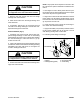
1. PTO pressure plate
2. PTO clutch lining
3. PTO flange hub
4. Flange yoke
Figure 12
PROCORE SR54 SHOWN
2
3
1
4
2
1. Cap screw
2. Spring
3. Nut
4. Flange yoke
Figure 13
1
2
4
3
1.125” (28.6 mm)
Chassis