
Service Manual


ProCore SR SeriesPage 7 -- 4Gearbox Service
4. Install output shaft assembly into gearbox housing:
A. Press ball bearing (item 8) onto output shaft.
Make sure that bearing is pressed fully to shaft shoul-
der.
B. Position bevel gear (item 11) and tapered bearing
cone (item 5) inside gearbox housing. Make sure
that bevel gear teeth mesh properly with gear on in-
put shaft. Slide output shaft through ball bearing
opening of housing, bevel gear, tapered bearing
cone and then tapered bearing opening of housing.
C. Insert tapered bearing cup (item 5) into bearing
bore of gearbox housing.
D. Install the removed shim(s) (item 3) and retaining
ring (item 2) into gearbox tapered bearing bore.
Make sure that retaining ring is fully seated in hous-
ing groove.
E. Install the removed shim(s) (item 3) and retaining
ring (item 2) into gearbox ball bearing bore. Make
sure that retaining ring is fully seated in housing
groove.
5. Check that there is no end play in the output shaft
and that output shaft bearings are not pre--loaded. If out-
put shaft end play is determined, add additional shim(s)
(item 3) as needed. If bearing pre--load (drag) is deter-
mined, remove shim(s).
6. Check gearbox backlash:
IMPORTANT: Correct engagement between bevel
gear and input shaft gear is critical to gearbox per-
formance and durability.
A. Position a dial indicator at the center of a tooth on
the bevel gear.
B. While preventing the input shaft from turning, ro-
tate the bevel gear and monitor the dial indicator
reading to check gearbox backlash. Allowable back-
lash is from 0.010” to 0.012” (0.25 to 0.30 mm).
IMPORTANT: If backlash adjustment is neces-
sary, do not simply remove shims from one side
of output shaft assembly as this would affect
output shaft endplay. Shims must be moved
from one side of the output shaft to the other side
during backlash adjustment.
C. If backlash is excessive (greater than 0.012”),
move shim(s) ( item 3) from ball bearing side of gear-
box to the tapered bearing side of gearbox. This shim
movement will move bevel gear closer to the input
shaft gear to reduce backlash.
D. If backlash is insufficient (less than 0.010”), move
shim(s) (item 3) from tapered bearing side of gear-
box to the ball bearing side. This shim movement will
move bevel gear away from the input shaft gear to in-
crease backlash.
E. Recheck backlash after any shim change. Re-
peat process until gearbox backlash is c orrect.
7. Apply light coating of PermatexR No. 2 to sealing
surface of cover plate (item 12). Use a soft face hammer
to drive cover plate into housing.
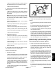
8. Carefully slide axle tube assemblies onto gearbox
shafts taking care to not damage seals. Align marker line
on housing and axle tube (Fig. 2). Secure axle tubes to
housing with socket head screws (item 19).
9. Apply a light coating of grease on lips and OD of input
seal (item 1). Install seal into gearbox bore taking care
to not damage seal during installation. Oil seal should be
flush to slightly recessed into gearbox bore.