
Service Manual


Page 4 – 58Hydraulic System
Sand Pro & Infield Pro 3040/5040
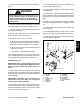
Hydrostat Service
1. Seal
2. Needle bearing
3. Cap screw (4 used)
4. Charge pump housing
5. Geroter assembly
6. O–ring
7. Implement relief valve
8. Plug with o–ring (2 used)
9. Charge relief valve
10. Retaining ring (2 used)
11. Trunnion shaft
12. Flat washer (2 used)
13. Seal (2 used)
14. Bearing
15. Retaining ring
16. Ball bearing
17. Retaining ring
18. Plug with o–ring
19. Pipe plug (2 used)
20. Needle bearing
21. Trunnion shaft
22. Woodruff key (2 used)
23. Swashplate
24. Cylinder block kit
25. Spring pin (4 used)
26. Flat washer
27. Valve plate
28. Gasket
29. Roller bearing
30. O–ring (2 used)
31. Cap screw (4 used)
32. Threaded plug with o–ring (2 used)
33. Acceleration valve (2 used)
34. Accelerator valve spring
35. Check valve assembly
36. Plug
37. O–ring
38. Spring
39. Check relief valve
40. Seal
41. Variable housing
42. End cap
43. Shaft
Figure 50
2
3
4
1
5
6
7
8
9
10
11
12
13
14
15
16
17
18 19
20
21
22
23
24
25
26
27
28
29
8
13
10
12
30
31
34
35
32
33
36
37
38
39
40
41
42
32
43
33
25
HYDROSTAT IS ILLUSTRATED FROM BELOW
FRONT
RIGHT
NOTE: For hydrostat repair information, see the Sau-
er–Danfoss (Sundstrand) 15 Series Repair Manual and
Service Manual at the end of this chapter.