
Service Manual


Page 4 – 52Hydraulic System
Sand Pro & Infield Pro 3040/5040
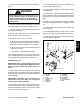
Pump Control Assembly
1. Pump lever
2. Cap screw
3. Cap screw
4. Ball bearing
5. Bearing spacer
6. Flange nut
7. Traction stud
8. Thrust washer
9. Neutral arm
10. Extension spring
11. Adjustment pin
12. Lock nut
13. Washer head screw (3 used)
14. Pump plate
15. Carriage screw
16. Switch plate
17. Neutral switch
18. Lock nut
19. Cap screw
20. Hex nut
21. Bushing (2 used)
22. Hydrostat
23. Ball joint
24. Jam nut
25. Traction rod
26. Lock nut
Figure 43
FRONT
RIGHT
2
1
5
4
3
6
13
10
9
8
7
18
11
14
12
15
16
17
19
20
6
21
22
23
24
25
26
Disassembly (Fig. 43)
1. Park machine on a level surface, lower attachment,
stop engine, apply parking brake and remove key from
ignition switch.
2. Remove two (2) cap screws and flat washers that se-
cure center shroud to machine (Fig. 46). Lift center
shroud from frame.
3. Remove cap screw, lock nut and flat washer that se-
cures traction rod to pump lever.
CAUTION
The extension spring is under tension and may
cause personal injury during removal. Use cau-
tion when removing spring from the pump arm.
4. Loosen lock nut on the bottom of the adjustment pin
to allow the extension spring to relax. Unhook spring
from anchor point of arm.