
Service Manual


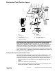


Table Of Contents
- Title Page
- Revision History
- Reader Comments
- Preface
- Table of Contents
- Chapter 1 : Safety
- Chapter 2 : Specifications and Maintenance
- Chapter 3 : Troubleshooting
- GEARS – The Systematic Approach to Defining, Diagnosing and Solving Problems
- Operator Advisories
- Machine and Engine Faults
- Using the InfoCenter Display for Troubleshooting
- General Hydraulic System Problems
- Traction System Problems
- Steering System Problems
- PTO System Problems
- 3-Point Hitch System Problems
- Attachment/Loader Problems
- Chapter 4 : Engine
- Chapter 5 : Hydraulic System
- General Information
- Traction Unit Operator’s Manual and Accessory Installation Instructions
- Relieving Pressure from the Hydraulic System
- Towing the Traction Unit
- Traction Circuit (Closed-Loop) Component Failure
- Hydraulic Hoses
- Installing Hydraulic Hoses and Tubes (O-Ring Face Seal)
- Installing the Hydraulic Fittings (SAE Straight Thread O-Ring Fittings)
- Hydraulic Schematic
- Hydraulic Flow Diagrams
- Testing the Hydraulic System
- Hydraulic Test Selection
- Traction Circuit Testing – Charge Pressure Test
- Traction Circuit Testing – Traction Pump (P1) and (P2) Flow and Relief Valve Tests
- Steering/Hitch Cylinder Circuit Testing – Steering Relief Valve (RV1) Pressure Test
- Steering/Hitch Cylinder Circuit Testing – Hitch Cylinder Test
- Steering/Hitch Cylinder Circuit Testing – Hitch Cylinder Relief Valve (RV2) Pressure Test
- Steering/Hitch Cylinder Circuit Testing – Gear Pump (P4) Flow Test
- Attachment/Loader Circuit Testing – Relief Valve Pressure Test
- Attachment/Loader Circuit Testing – Gear Pump (P3) Flow Test
- Adjustments
- Service and Repairs
- General Precautions for Removing and Installing the Hydraulic System Components
- Checking the Hydraulic Lines and Hoses
- Flushing the Hydraulic System
- Filtering the Closed-Loop Traction Circuit
- Priming the Hydraulic Pumps
- Charging the Hydraulic System
- Hydraulic Tank
- Hydraulic Fluid Cooler
- Tandem Piston (Traction) Pump (P1) and (P2)
- Tandem Piston (Traction) Pump (P1) and (P2) Service
- Gear Pump (P3) and (P4)
- Gear Pump (P3) and (P4) Service
- Axle Motors
- Axle Motor Service
- Axle Differential Locks
- Hydraulic Brake Assembly
- Hydraulic Brake Service
- Main Hydraulic Manifold
- Main Manifold Service
- Cartridge Valve Service
- Steering Control Valve
- Steering Control Valve Service
- Steering Cylinders
- Steering Cylinder Service
- 3-Point Hitch Cylinders
- 3-Point Hitch Cylinder Service
- PTO Clutch
- Auxiliary Load Valve
- Auxiliary Load Valve Service
- Front Loader Control Valve
- Front Loader Control Valve Service
- Selector Control Valve Manifolds (optional)
- Selector Control Valve Manifold (optional) Service
- General Information
- Chapter 6 : Electrical System
- General Information
- Electrical Drawings
- Electrical System Quick Checks
- Electrical Component Testing
- Fuses
- Fusible Link Harness
- CAN bus
- Primary Controller (T1: TEC)
- Status Display Controller (T2: TDM)
- InchMode Controller (T3: TEC) (optional)
- Key Switch
- Mode Selector
- Parking Brake Switch
- Power Take Off (PTO) Enable Switch
- Economy (ECO) Mode Switch
- Hydraulic Auxiliary (AUX) Switch
- Seat Switch
- Paddle (3-Point Hitch) and Transmission Lever Switches
- Headlight/Worklight Switch
- Cruise Control Off/On/Set Switch
- Cruise Control Speed Increase/Decrease Switch
- Air Conditioning On/Off Switch
- Heater/Air Conditioning Blower Speed Switch
- InchMode Enable Switch (optional)
- InchMode Raise/Lower and Forward/Reverse Switches (optional)
- Loader Selector Control Valve (SCV) Switch (optional)
- Traction Pedal Assembly
- Decelerator Pedal Position Sensor
- Decelerator Pedal Neutral Switch
- 3-Point Hitch Position Sensor
- Hydraulic Fluid Temperature Sender
- Speed Sensors
- Traction Pressure Sensors
- Fuel Pump
- Fuel Level Sender
- Warning Buzzer
- Relays with 4 Terminals
- Relays with 5 Terminals
- Diode Assemblies
- Resistor Assembly
- CAN bus Terminator Resistors
- Hydraulic Solenoid Valve Coils
- Tandem Traction (Piston) Pump Control Solenoid Coils
- Service and Repairs
- Chapter 7 : Traction and PTO Drive
- Chapter 8 : Chassis
- Chapter 9 : Operator Cab
- Appendix A: Foldout Drawings
- Electrical Drawing Designations
- Hydraulic Schematic
- Electrical Schematic (part 1 of 3)
- Electrical Schematic (part 2 of 3)
- Electrical Schematic (part 3 of 3)
- Wire Harness Drawing – Frame
- Wire Harness Diagram – Frame
- Wire Harness Drawing – Platform
- Wire Harness Diagram – Platform
- Wire Harness Diagram – Platform (continued)
- Wire Harness Drawing – Engine
- Wire Harness Diagram – Engine
- Wire Harness – Headlights
- Wire Harness – Cab Rooftop
- Wire Harness – Cab Control Panel
- Wire Harness – Cab Heat/Air Conditioning
- Wire Harness – InchMode (optional)
- Wire Harness – Loader Selector Control Valve (SCV) Switch (optional)
- Wire Harness – Loader Selector Control Valve (SCV) Valve (optional)
- Wire Harness – Rear Selector Control Valve (SCV) Kit (optional)
- Wire Harness – Cab Work Light Kit (optional)
- Wire Harness – Domestic Road Light Kit (optional)
- Wire Harness – Turn Signal/Hazard Lights (optional)
- Wire Harness – International Road Light Kit (optional)

TractionPedalAssembly
g257736
Figure88
Thetractionpedalassemblyincludes2analoghalleffectsensorsthatdonot
requirecalibration.Thesensorsoperateon5VDCsuppliedbytheT1:TEC.
SignalvoltagefromthepedalsensorsareusedbytheT1:TEC(alongwith
informationfromadditionalinputs)todetermineappropriatecurrentowtothe
tandempiston(traction)pumpcontrolvalves.Thesensorsignalsarealso
constantlymonitoredfortractionfaultdetection.
Ifatractionpedalfaultoccurswhilethemachineismoving,themachinewill
slowlycometoastop.Thedeceleratorpedalcanbeusedtostopthemachine
soonerifnecessary.Atractionpedalfaultwilldisabletractioncontroluntilthe
ignitionkeyiscycledOFFandON.
TestingtheTractionPedalAssembly
ThetractionpedalassemblyanditscircuitwiringcanbetestedasaT1:TEC
inputusingtheInfoCenterDisplay;refertoUsingtheInfoCenterDisplayfor
Troubleshooting(page3–23).Iftestingdeterminesthattheassemblyand
itscircuitwiringarenotfunctioningcorrectly,proceedwiththefollowingtest
procedure:
1.Parkthemachineonalevelsurface,loweranyattachmentsandstopthe
engine.
2.Disconnecttheplatformwireharnessfromthetractionpedal.Checkthe
pedalandtheharnessconnectorfordamageorcorrosion.
3.ConnectpinsCandDtoa5VDCpowersupply,andconnectpinsBand
Etoground.
4.Usingamultimeter(DCvoltagesetting)withthetractionpedalatrest,less
than0.62VDCshouldbepresentatpinAandlessthan0.75VDCshouldbe
presentatpinF .
5.Usingamultimeter(DCvoltagesetting)withthetractionpedalfully
depressed,2.5VDCshouldbepresentatpinAand4.5VDCshouldbe
presentatpinF .
6.Replacethetractionpedalassemblyifnecessary.
7.Ifthetractionpedaltestscorrectlyandacircuitproblemstillexists,checkthe
wireharnesses;refertoAppendixA(pageA–1).
Outcross9060
Page6–45
ElectricalSystem:ElectricalComponentTesting
18234SLRevD