
Service Manual


Workman HD SeriesPage 8 -- 24Electrical System
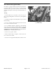
Speed Sensor (Workman HDX and HDX--D)
The speed sensor is attached to the upper transaxle
cover (Fig. 34). It uses a magnetically based, Hall Effect
integrated circuit. As the differential in the transaxle
turns, the sensor accurately senses the movement of
thedifferentialringgearteethpassingbythesensor.The
redstripedconnectorwireisthesensorpositivelead,the
black wire is the ground lead and the gray striped wire
is the signal output.
Testing
1. Park machine on a level surface, raise bed, stop en-
gine, apply parking brake and remove key from ignition
switch.
2. Install bed support on bed lift cylinder to prevent bed
from lowering.
3. Locate traction s peed sensor on the transaxle as-
sembly. Disconnect thewireharness connector fromthe
traction speed sensor.
4. Remove flange head screw that secures speed sen-
sor to transaxle. Remove speed sensor from transaxle.
IMPORTANT: Incorrect jumper wire connections
during testing can damage the sensor.
5. Using a +12 VDC battery, a multimeter, a 1K ohm re-
sistor and appropriate jumper wires, connect the battery
and multimeter to the speed sensor using Figure 35 as
a guide.
6. Set multimeter to DC volts setting.
7. The multimeter should display verylow v oltage when
ametal object isheld nearthe sensor tip.Themultimeter
should display battery voltage when the metal object is
moved away from the sensor tip.
8. Aftertestingiscomplete,removejumperwires,resis-
tor and multimeter leads from sensor connector.
9. Replace speed sensor if necessary.
10.Install speed sensor into transaxle and secure with
flangeheadscrew. Reconnect speed sensortowirehar-
ness.
11.Remove bed support from lift cylinder and lower bed.
1. Speed sensor 2. Flange head screw
Figure 34
1
2
1. Speed sensor
2. Sensor tip
3. Sensor connector
4. Red striped wire
5. Gray striped wire
6. Black wire
Figure 35
BAC
--
+
12 VDC
6
4
2
3
1
5
1K ohm
resistor