
Operator's Manual


18
2. Remove capscrew, washers and locknut securing battery
hold down to battery base. Remove hold down and slide
battery out of battery base.
3. Remove filler caps from battery and slowly fill each
cell until electrolyte is just above the plates.
4. Replace filler caps and connect a 3 to 4 amp battery
charger to the battery posts. Charge the battery at a rate
of 3 to 4 amperes for 4 to 8 hours.
Charging the battery produces gasses that can
explode.
Never smoke near the battery and keep sparks and
flames away from battery.
Warning
5. When battery is charged, disconnect charger from
electrical outlet and battery posts.
2
1
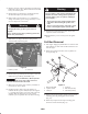
Figure 8
1. Positive (+) cable 2. Hold down
6. Remove filler caps. Slowly add electrolyte to each cell
until level is up to fill ring. Install filler caps.
Important Do not overfill battery. Electrolyte will
overflow onto other parts of the vehicle and severe
corrosion and deterioration will result.
7. Slide battery into battery base so battery terminals are
toward the rear of the vehicle.
8. Install the positive cable (red) to the positive (+)
terminal and the negative cable (black) to the negative
(—) terminal of the battery and secure with capscrews
and nuts. Slide the rubber boot over the positive
terminal to prevent possible short–out from occurring.
Incorrect battery cable routing could damage the
machine and cables causing sparks. Sparks can
cause the battery gasses to explode, resulting in
personal injury.
• Always disconnect the negative (black) battery
cable before disconnecting the positive (red)
cable.
• Always connect the positive (red) battery cable
before connecting the negative (black) cable.
Warning
9. Install battery hold down and secure to base with
capscrew, washers and locknut.
10. Reinstall battery cover to battery base and tighten
knobs.
Full Bed Removal
1. Start engine. Engage hydraulic lift lever and lower bed
until cylinders are loose in slots. Release lift lever and
turn off engine.
2. Remove lynch pins from outer ends of cylinder rod
clevis pins (Fig. 9).
2 3
1
4
5
6
Figure 9
1. Bed mounting plate
2. Cylinder rod end
3. Clevis pin
4. Lynch pin
5. Rear slots (Full bed)
6. Front slots (2/3 bed)
3. Remove clevis pins securing cylinder rod ends to bed
mounting plates by pushing pins towards inside
(Fig. 10).
4. Remove lynch pins and clevis pins securing pivot
brackets to frame channels (Fig. 10).