
Operator's Manual


47
3. Loosen jam nuts securing yoke to master cylinder shaft
(Fig. 60).
4. Adjust yoke until its holes align with hole in brake
pedal pivot. Secure yoke to pedal pivot with clevis pin
and cotter pin.
5. Tighten jam nuts securing yoke to master cylinder shaft.
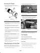
1
2
Figure 61
1. Brake pedal 2. Clutch pedal
Adjusting Clutch Pedal
Check adjustment every 200 hours.
Note: The clutch pedal cable can be adjusted at the bell
housing or at the clutch pedal pivot. Front hood can be
removed to ease access to pedal pivot.
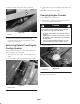
Bell Housing Method
1. Loosen jam nuts securing clutch cable to bracket on bell
housing (Fig. 62).
1
2
3
4
Figure 62
1. Clutch cable
2. Jam nuts
3. Return spring
4. Ball joint
Note: Ball joint may be removed and rotated, if additional
adjustment is required.
2. Disconnect return spring from clutch lever.
3. Adjust jam nuts/or ball joint until bottom rear edge of
clutch pedal is 3.75” + .12” from top of floor plate
diamond pattern, when an 4 lb. force is applied to pedal.
Note: Force is applied so release bearing lightly contacts
pressure plate fingers.
4. Reconnect return spring to clutch lever.
5. Verify that rear edge of clutch pedal is 5.5” +
.12” from
top of floor plate diamond pattern. If dimension is not
attained, adjust clutch pedal upstop.
Note: The clutch free play should never be less than .75”.
6. Tighten jam nuts after adjustment has been attained.
7. Recheck clutch safety switch adjustment (Fig. 63).
Engine must not crank unless clutch pedal is
1.25” ±.12” from floor. If an adjustment is required,
loosen switch jam nuts and adjust up or down.
1
Figure 63
1. Clutch switch
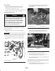
Clutch Pedal Pivot Method
1. Remove nut securing clutch cable ball joint end to
clutch pedal pivot (Fig. 64).
1
2
3
4
Figure 64
1. Clutch pedal pivot
2. Ball joint end
3. Clutch cable
4. Frame bracket
2. Loosen jam nuts securing clutch cable to frame bracket.