
Service Manual


Removal (Fig. 31)
1. Park vehicle on a level surface, shut engine off and
engage the parking brake.
2. Read the
General Precautions for Removing and
Installing Hydraulic System Components at the begin-
ning of
the Service and Repairs section of this chapter.
CAUTION
Before performing any service or repair on hy-
draulic system components, relieve system
pressure to avoid injury from pressurized hy-
draulic oil. Stop the engine, remove key from the
ignition switch, rotate the steering wheel in both
directions, lower or support the bed and operate
other hydraulic accessories.
3. Label and disconnect hydraulic hoses from steering
cylinder. Install caps or plugs in hoses to prevent con-
tamination and
leakage of hydraulic oil. Install plugs in
cylinder ports.
4. Remove steering
cylinder from vehicle using Figures
31 and 32 as guides.
Installation (Fig.
31)
1. If ball
joint was removed from cylinder shaft, fully re-
tract cylinder
shaft and thread ball joint onto shaft. Adjust
center to center length to dimension shown in Figure 33
before tightening jam nut. Torque jam nut 50 ft--lb (68
N--m).
2. Install s
teering cylinder to vehicle using Figures 31
and 32 as guides.
3. Replace o--rings on
hydraulic hoses and fittings. R e-
move caps
and plugs from hoses and fittings. Connect
hydraulic hoses to steering cylinder.
4. Check oil
level in transaxle (see Operator’s Manual).
Add Dexron III ATF if necessary.
5. Start t
he engine, operate at idle speed and rotate the
steering wheel in both directions until air is out of hydrau-
lic syst
em.
6. Stop the
engine and check oil level in transaxle (see
Operator’s Manual). Add Dexron III ATF if necessary.
7. Check f
ront wheel alignment and adjust as needed
(see Front Wheel Alignment in the Service and Repair
section of Chapter 7 -- Chassis).
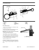
1. O--ring
2. 45
o
hydraulic fitting
3. O--ring
4. O--ring
5. 90
o
hydraulic fitting
6. O--ring
7. Ball joint
8. Jam nut
Figure 32
1
2
4
3
5
6
8
7
50 ft--lb
(68 N--m)
14.520” (36.88 cm) for 2WD
15.040” (38.20 cm) for 4WD
CYLINDER LENGTH WHEN FULLY RETRACTED
Figure 33
Hydraulic
System
Workman 3000/4000 Series Page 9 -- 39
Rev. A
Hydraulic System