
Service Manual


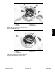


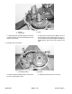


Table Of Contents
- Title Page
- Revision History
- Reader Comments
- Preface
- Table Of Contents
- 1 - Safety
- 2 - Product Records and Maintenance
- 3 - Diesel Engine
- KUBOTA WORKSHOP MANUAL, DIESEL ENGINE, SM-E3B SERIES
- 4 - Drive Train
- 5 - Electrical System
- Table of Contents
- General Information
- Special Tools
- Troubleshooting
- Electrical System Quick Checks
- Component Testing
- Ignition Switch
- Indicator Lights
- Fuse Blocks
- Fusible Links
- Hour Meter
- Headlight Switch
- Brake Switch
- Main Power and Glow Relays
- Start Relay
- Glow Plug Controller
- Engine Run Solenoid
- Over Temperature Switch
- Fuel Pump
- Oil Pressure Switch
- Backup Alarm (Optional Kit)
- Backup Switch (Optional Kit)
- Windshield Washer/Wiper Switch (Machines with Operator Cab)
- Diode Assembly (Model 07236)
- Service and Repairs
- 6 - Chassis
- Table of Contents
- Specifications
- General Information
- Special Tools
- Troubleshooting
- Adjustments
- Service and Repairs
- Check Tire Pressure
- Inspect Tires and Wheels
- Upper Steering (Serial Numbers Below: 316000001)
- Steering Gearbox (Serial Numbers Below: 316000001)
- Lower Steering and Front Wheels (Serial Numbers Below: 316000001)
- Steering Assembly (Serial Numbers Above: 316000001)
- Steering Rack Assembly Service (Serial Numbers Above: 316000001)
- Front Shock Absorbers
- A−arms and Front Suspension (Serial Number Below: 316000001)
- A−arms and Front Suspension (Serial Number Above: 316000001)
- Frame Pivot Yoke
- Swing Arm
- Parking Brake
- Rear Wheels and Brakes
- Rear Brake Service
- Front Brake Calipers
- Front Brake Caliper Service
- Brake Master Cylinder
- Brake Master Cylinder Service
- Bleed Brake System
- Seat Base
- Front Hood
- Cargo Box
- Windshield Wiper Assembly (Machines with Operator Cab)
- 7 - Electrical Drawings
- Table of Contents
- Electrical Schematic (Serial Number Below315000000)
- Electrical Schematic (Serial Number315000001 to 403450000)
- Electrical Schematic (Serial NumberAbove 403450001)
- Glow Plug Circuits
- Start Circuits
- Run Circuits
- Main Electrical Harness (Serial NumberBelow 315000000)
- Main Electrical Harness (Serial NumberBelow 315000000)
- Main Electrical Harness (Serial Number315000001 to 403450000)
- Main Electrical Harness (Serial Number315000001 to 403450000)
- Main Electrical Harness (Serial NumberAbove 403450001)
- Main Electrical Harness (Serial NumberAbove 403450001)
- Engine Electrical Harness
- Heater Kit--Wire Harness Drawing
- Cab Headliner--Wire Harness Drawing

Workman MDX--D Drive TrainPage 4 -- 33
2. Assemble the center shaft assembly.
1. Pin clutch
2. Center shaft
3. Gear 47
4. Gear 55
5. Collar
6. Gear (small)
7. Bearing
8. Bearing
9. Spacer
Figure 39
7
4
6
3
5
5
8
2
1
9
5.386” to 5.398”
(136.8 to 137.1 mm)
NOTE: Before assembling, apply molybdenum disul-
fide grease to the inside of gears 47 and 55.
A. Slide pin clutch onto the centershaft. Install gears
47 and 55 onto shaft noting correct orientation of
gears. Slide collars, small gear and spacer onto the
center shaft.
1. Ball bearing 2. Ball bearing
Figure 40
1
2
B. Press ball bearings onto the center shaft using a
bearing press.
C. Make sure distance from one ball bearing outer
edge to the o ther ball bearing outer edge is 5.386” to
5.398” (136.8 to 137.1 mm) (Fig. 39).
Drive Train