
Service Manual


Table Of Contents
- Title Page
- Revision History
- Reader Comments
- Preface
- Table Of Contents
- 1 - Safety
- 2 - Product Records and Maintenance
- 3 - Diesel Engine
- KUBOTA WORKSHOP MANUAL, DIESEL ENGINE, SM-E3B SERIES
- 4 - Drive Train
- 5 - Electrical System
- Table of Contents
- General Information
- Special Tools
- Troubleshooting
- Electrical System Quick Checks
- Component Testing
- Ignition Switch
- Indicator Lights
- Fuse Blocks
- Fusible Links
- Hour Meter
- Headlight Switch
- Brake Switch
- Main Power and Glow Relays
- Start Relay
- Glow Plug Controller
- Engine Run Solenoid
- Over Temperature Switch
- Fuel Pump
- Oil Pressure Switch
- Backup Alarm (Optional Kit)
- Backup Switch (Optional Kit)
- Windshield Washer/Wiper Switch (Machines with Operator Cab)
- Diode Assembly (Model 07236)
- Service and Repairs
- 6 - Chassis
- Table of Contents
- Specifications
- General Information
- Special Tools
- Troubleshooting
- Adjustments
- Service and Repairs
- Check Tire Pressure
- Inspect Tires and Wheels
- Upper Steering (Serial Numbers Below: 316000001)
- Steering Gearbox (Serial Numbers Below: 316000001)
- Lower Steering and Front Wheels (Serial Numbers Below: 316000001)
- Steering Assembly (Serial Numbers Above: 316000001)
- Steering Rack Assembly Service (Serial Numbers Above: 316000001)
- Front Shock Absorbers
- A−arms and Front Suspension (Serial Number Below: 316000001)
- A−arms and Front Suspension (Serial Number Above: 316000001)
- Frame Pivot Yoke
- Swing Arm
- Parking Brake
- Rear Wheels and Brakes
- Rear Brake Service
- Front Brake Calipers
- Front Brake Caliper Service
- Brake Master Cylinder
- Brake Master Cylinder Service
- Bleed Brake System
- Seat Base
- Front Hood
- Cargo Box
- Windshield Wiper Assembly (Machines with Operator Cab)
- 7 - Electrical Drawings
- Table of Contents
- Electrical Schematic (Serial Number Below315000000)
- Electrical Schematic (Serial Number315000001 to 403450000)
- Electrical Schematic (Serial NumberAbove 403450001)
- Glow Plug Circuits
- Start Circuits
- Run Circuits
- Main Electrical Harness (Serial NumberBelow 315000000)
- Main Electrical Harness (Serial NumberBelow 315000000)
- Main Electrical Harness (Serial Number315000001 to 403450000)
- Main Electrical Harness (Serial Number315000001 to 403450000)
- Main Electrical Harness (Serial NumberAbove 403450001)
- Main Electrical Harness (Serial NumberAbove 403450001)
- Engine Electrical Harness
- Heater Kit--Wire Harness Drawing
- Cab Headliner--Wire Harness Drawing
Workman MDX−DPage 6 − 36Chassis
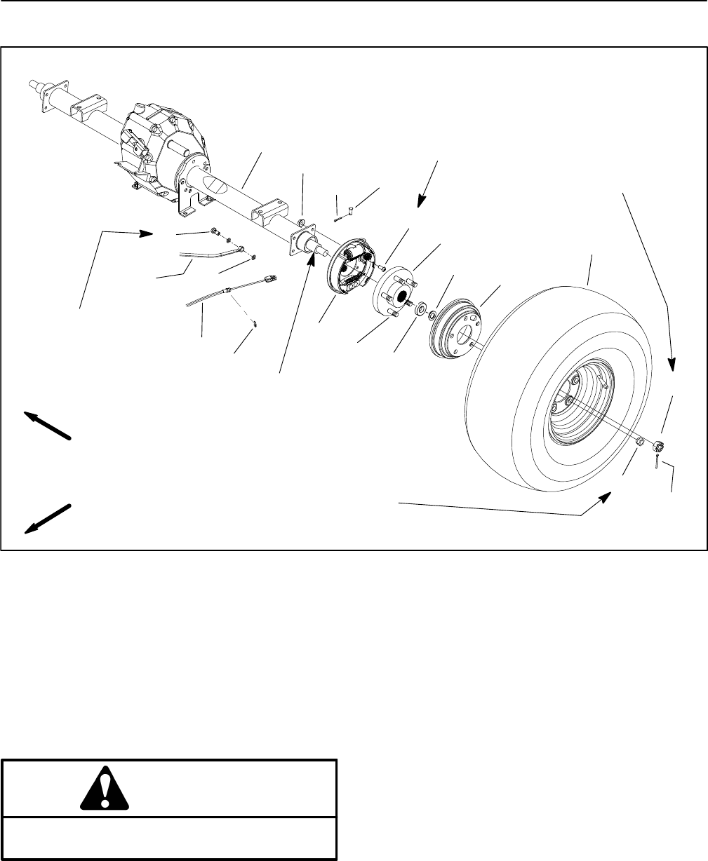
Rear Wheels and Brakes
1. Wheel assembly
2. Lug nut (5 used per hub)
3. Castle nut
4. Brake drum
5. Socket head screw (4 used per brake)
6. Brake assembly (LH shown)
7. Clevis pin
8. Cotter pin
9. Cotter pin
10. Flange nut (4 used per brake)
11. Transaxle
12. Parking brake cable (2 used)
13. Wheel hub
14. Washer
15. Spring washer
16. Wheel stud (5 used per hub)
17. Retaining ring
18. Rear brake line
19. Banjo bolt
20. Banjo washer (2 used per brake)
Figure 29
FRONT
RIGHT
10
9
8
7
6
5
4
1
2
11
12
3
80 to 90 ft−lb
(109 to 122 N−m)
120 ft−lb
(163 N−m)
13
14
15
20 ft−lb
(27 N−m)
Antiseize
Lubricant
16
17
18
19
20
15 to 21 ft−lb
(21 to 28 N−m)
Removal (Fig. 29)
1. Park machine on a level surface, stop engine, set
parking brake and remove key from the ignition switch.
WARNING
Before jacking up the machine, review and follow
Jacking Instructions in Chapter 1 − Safety.
2. Chock wheels not being jacked up. Lift rear wheel off
the ground using a jack and support vehicle with ap-
propriate jack stand beneath the frame.
3. Remove five (5) lug nuts, wheel assembly and brake
drum from the wheel hub.
4. Remove cotter pin from the castle nut and transaxle
shaft. Remove castle nut, spring washer and washer
from the shaft. Remove the wheel hub from the shaft.
NOTE: The brake assembly can be removed from the
transaxle shaft for disassembly.
5. If required, remove brake assembly as follows:
A. Remove cotter pin and clevis pin securing the
parking brake cable to the parking brake lever on the
rear of the brake assembly.
B. Clean hydraulic brake line area of brake assem-
bly to prevent contamination (Fig. 30). Loosen and
disconnect brake line from wheel cylinder. Plug
brake line and position it away from brake assembly.
Discard two (2) banjo washers.