
Service Manual


IMPORTANT:When bearing cones (29) are removed
removed from the differential case (27) they should
replaced with new ones. When installing new bear-
ing cones to the differential case, use original shims
(31) or new shims of the same thickness.
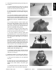
8. Press bearing cone (29) onto the differential case
(27) (Fig. 53).
Figure 53
9. Position ring gear (32) to the differential case (27).
Secure ring gear to the case with five cap screws (26)
i
n a criss–cross pattern so the gear is pulled evenly into
place. Torque cap screws from 58 to 65 ft–lb ( 8.1 to 9.0
kg–m) (Fig. 54).
Note: The bearing cradle are designed to apply a
slight preload to the bearings. Therefore, it is important
to push both bearing assemblies simultaneously into
their cradles.
IMPORTANT:If new bearing cones (29) were
installed o
nto the differential case (27), new bearing
cups (30) must be installed to the bearing cradles.
10. Place bearing cups (30) onto bearing cones (29).
Install bearing assemblies into the bearing cradles of
the
carrier assembly (15). Make sure bearing cups (30) are
matched to the proper bearing cradle and bearing cone
(29) (Fig. 55).
IMPORTANT:The bearing caps are marked for iden-
tification. Place caps back in the same position dur-
ing reassembly (Fig. 56).
11. Secure bearing caps to their original positions on
t
he bearing cradles with for cap screws (11). Torque cap
screws from 30 to 45 ft–lb (4.1 to 6.2 kg–m) (Fig. 56).
Figure 54
Figure 55
MARKING
MARKING
Figure 56
Front Wheell Drive Section (4WD) Page 10
– 28
Rev. B
Workman 4000 Series