
Service Manual


Disassembly
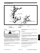
1. Pry retaining ring (Fig. 29, Item 1) out of housing
groove with a screwdriver
.
2. Turn stub shaft (Item 36) to the left until plug (Item 2)
on opposite end is forced out of cylinder
, then remove
seal (Item 3).
3. Remove plug (Item 6) from rack piston (Fig. 30).
4. Remove nut (Fig. 29, Item 16), bolts (Item 17), side
cover (Item 15) and gasket (Item 14), then turn adjuster
Figure 31
screw right until side cover (Item 15) separates from pit-
Plug
Socket
Ball
retainer
tool
man shaft (Item 13).
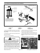
5. Remove pitman shaft, then turn stub shaft (Item 36)
left until pitman shaft teeth and rack piston (Item 1
1) dis-
engage.
6. Remove retaining ring (Item 43), washers (Item 44)
and seals (Item 45, 46), then remove bearing (Item 47)
(Fig. 31).
7. Remove rack piston and balls as follows:
A. Insert ball retainer tool into rack piston bore with
Figure 32
pilot seated into end of worm (Fig. 30).
B. Hold tool against worm and turn stub shaft (Fig.
29, Item 36) to left. Rack piston (Item 1
1) will be
forced onto the tool.
C. Hold tool and pull rack piston toward handle until
it is against flange. This will prevent balls (Item 10)
from falling out.
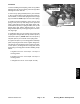
8. Remove adjuster nut (Fig. 29, Item 25) (Fig. 32).
Figure 33
9. Remove adjuster plug (Fig. 29, Item 26) using a span-
ner wrench (Fig. 33).
Adjuster plug
Stub shaft
Spanner
wrench
Figure 34
Steering, Brakes
& Suspension
Workman 3000 Series Page 7 – 27 Steering, Brakes and Supension