
Service Manual


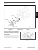

Piston and Connecting Rod
1
2
3
4
5
6
7
8
9
11
10
12
20 – 23 Nm
(14 – 17 ft–lb)
Figure 199
1. Nut 5. Connecting rod bearing
2. Connecting rod cap 6. Bolt
3. Connecting rod assembly 7. No. 1 piston ring
4. Piston and connecting rod 8. No. 2 piston ring
Disassemble and assemble parts as shown in illustra-
tion above. Also use the following instructions for specif-
ic points of disassembly, inspection and reassembly.
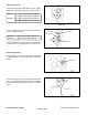
Disassembly of Piston and Connecting Rod
1. Mark big end of connecting rod with cylinder number
for proper reassembly
.
Cylinder No.
9. Oil ring
10. Piston pin
11. Piston
12. Connecting rod
Figure 200
Liquid Cooled Gas Engine
Page 3
– 96
Workman 3000/4000 Series