
Service Manual


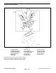


2. Remove plug on left side of cylinder block and insert
a 8 mm (.32 in.) rod to lock counterbalance shaft. Re-
move flange bolt securing oil pump drive gear. Remove
oil pump drive gear.
Rod
Figure 184
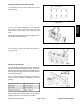
3. Remove rear cover. Use special tool to drive out
counterbalance shaft front bearing from cylinder block.
Figure 185
4. Use special tool to drive out counterbalance shaft
rear bearing from cylinder block.
Figure 186
Front Case, Counterbalance Shaft
and Oil Pan Inspection
1. Inspect counterbalance shaft oil holes for clogging
a
nd clean if necessary. Check journal for seizure, dam-
age and contact with bearing. Replace bearings and/or
counterbalance shaft if damaged.
Figure 187
Liquid Cooled Gas Engine
Page 3
– 92
Workman 3000/4000 Series