
Service Manual


2
3
Carburetor Service
31
36
37
39
40
42
43
44
0.8 Nm
2 Nm
38
0.8 Nm
(0.6 ft–lb)
(1.6 ft–lb)
(0.6 ft–lb)
20
21
3.5 Nm
(2.5 ft–lb)
*47
1
*48
22
*49
23
*50
45
24
46
51
SEE NOTE BELOW
35
34
32
33
2.0 Nm
(1.6 ft–lb)
30
27
26
28
4
5
6
7
8
9
10
12
13
14
15
16
17
18
19
3.5 Nm
6 Nm
(2.5 ft–lb)
(4 ft–lb)
2 Nm
29
41
(1.6 ft–lb)
3G80029
3.5 Nm
25
(2.5 ft–lb)
3G80030
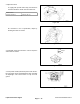
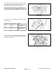
Figure 138 Figure 139
1. Vacuum hose kit 18. Diaphragm 35. O–ring
2. Retainer 19. Spring 36. Plug
3. Fuel cut solenoid valve (FCSV) 20. Clip 37. Plate
4. O–ring 21. Clip 38. Pilot jet
5. Throttle wire bracket 22. Piston cover 39. Main jet
6. Auto–choke body assembly
23. Spring 40. O–ring
7. Gasket 24. Piston valve assembly
41. O–ring
8. Ring 25. Float chamber body
42. Power jet
9. Ring 26. O
–ring 43. Jet block
10. Lever (cam follower) 27. Retainer 44. O
–ring
12. Guide ring 28. W
eight 45. Idle speed adjusting screw (SAS)
13. Ring 29. Ball 46. Spring
14. Throttle lever 30. Pin *47. Mixture adjusting screw (MAS) (see Note)
15. Guide ring 31. Float *48. Spring (see Note)
17. Pump cover 32. Needle valve *49. W
asher (see Note)
33. Retainer *50. Gasket (see Note)
34. Needle valve seat 51. Mixing body
Disassemble and assemble parts as shown in illustra- Carburetor Disassembly
tion above. Also use the following instructions for specif-
ic points of disassembly, inspection and reassembly.
IMPORTANT: Do not disassemble the following
items:
Note: All
carburetors with a TEB identification mark – Auto–choke body assembly (Item 6).
have a tamper–resistant idle Mixture Adjusting Screw – Throttle valve and throttle shaft.
(MAS). These parts cannot be replaced: this would be – Piston valve assembly (Item 24).
in violation of U.S. Environmental Protection Agency – Vapor separator tank plate.
(EPA) and California Air Resources Board (CARB) regu-
lations. If these parts need replacement, the entire car-
buretor must be replaced.
Workman 3000/4000 Series
Page 3
– 73
Rev. B
Liquid Cooled Gas Engine
Liquid Cooled
Gas Engine