
Service Manual


Rev. D
Workman 3000 SeriesPage 7 – 16Steering, Brakes and Suspension
Master Brake Cylinder Service
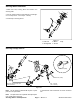
Note: Unlike older versions (Fig. 12) of the master cyl-
inder, newer versions (Fig. 13) have the reservoir at-
tached to the cylinder.
Disassembly
1. Remove pipe adapter (Item 1), if installed, and adapt-
er or flange seal (Item 2). Push in on the push rod so the
stop pin (Item 3) can can be removed.
2. Disconnect lower end of the dust cover (Item 6) from
the housing.
3. Push in on the push rod and remove circlip (Item 8),
then remove push rod with dust cover and clevis.
4. Remove primary piston assembly (Item 10) and sec-
ondary piston assembly (Item 11).
Inspection
1. Clean all metal parts with isopropyl alcohol, then
clean out and dry grooves and passageways with com-
pressed air. Make sure cylinder bore and component
pieces are thoroughly clean.
2. Check cylinder bore and pistons and springs for dam-
age or excessive wear. Replace brake cylinder assem-
bly if signs of pitting, scoring or cracks are evident.
Assembly
1. Apply a film of clean brake fluid to cylinder bore and
piston assemblies.
2. Install secondary piston assembly (Item 10) and pri-
mary piston assembly (Item 11).
3. Install retainer washer (Item 9).
4. Install push rod (Item 7) and secure in place with cir-
clip (Item 8). Install lower end of dust cover (Item 6) to
housing.
5. Push in on push rod so stop pin can can be installed
to retain secondary piston assembly, then install adapt-
er or flange seal (Item 2) and pipe adapter (Item 1) if
installed.
6. Adjust brake pedal and bleed brakes after installing
in machine.
1
2
3
11
4
5
6
7
8
9
10
Figure 12
1. Pipe adapter 7. Push rod
2. Adapter 8. Circlip
3. Stop pin 9. Retainer washer
4. Clevis 10. Primary piston assembly
5. Nut 11. Secondary piston assembly
6. Dust cover
3
4
7
12
2
5
8
10
1
11
6
9
1. Master cylinder reservoir
2. Flange seal
3. Stop pin
4. Clevis
5. Nut
6. Dust cover
7. Push rod
8. Circlip
9. Retainer washer
10. Primary piston assy.
11. Secondary piston assy.
12. Cap assembly
Figure 13