
Service Manual


Testing
This section will define given components, and the tests
that can be performed on those components, when
those parts are disconnected from the electrical system.
For accurate resistance and/or continuity checks, elec-
trically disconnect the component being tested from the
circuit (e.g. unplug the clutch switch connector before
doing a continuity check).
Note: Electrical
troubleshooting of any 12 Volt power
connection can also be performed through voltage drop
tests without disconnection of the component.
CAUTION
connected.
When testing electrical components for continu-
ity with a volt–ohm meter or continuity tester,
make sure that power to the circuit has been dis-
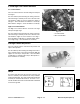
Ignition Key Switch
The ignition (key) switch has three positions (OFF,
START and RUN). The terminals are marked as shown
in Figure 4.The circuitry of the ignition switch is shown
in the chart (Fig. 5). With the use of a continuity tester,
the switch functions may be tested to determine whether
all circuits are being completed while the key is moved
to each position.
A
Y
B
I
X
S
Figure 4
POSITION CONTINUITY
AMONG
TERMINALS
OTHER
CIRCUITS
MADE
1. OFF NONE NONE
2. RUN B+A+I X+Y
3. START B+S+I NONE
Figure 5
Workman 3000/4000 Series Page 8 – 17 Electrical System (Rev
. G)
Electrical
System)