
Service Manual


Starter Service
1
2
3
4
5
6
7
8
9
10
11
12
13
14
15
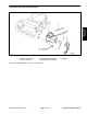
Figure 114
1. Magnetic switch 6. Brush holder 11. Pinion stop nut
2. Boot 7. Yoke assembly 12. Snap ring
3. Rear bracket assembly 8. Front bracket assembly 13. Pinion stop nut
4. Insulator 9. Plate washer 14. Overrunning clutch
5. Brush spring 10. Drive lever 15. Armature
Disassemble and assemble parts as shown in illustra-
tion above. Also use the following instructions for specif-
ic points of disassembly, inspection and reassembly.
Starter Disassembly
1. Disconnect lead wire from M terminal of magnetic
switch
before removing magnetic switch.
Figure 115
2. When removing brush holder, remove brush, brush
spring and brush holder
, in that order. NOTE: Be sure
not to disconnect yoke from front bracket or the brush
spring will jump out.
Liquid Cooled
Gas Engine
Figure 116
Workman 3000/4000 Series
Page 3
– 65
Liquid Cooled Gas Engine