
Service Manual


CuttingUnitAssembly
g261511
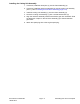
Figure79
1.Cuttingunitassembly4.Dowelpin(4each)
2.Reeldriveassembly5.Frameassembly
3.Socketheadscrew(4each)
RemovingtheCuttingUnitAssembly
Note:RefertoFigure79duringthisprocedure.
1.Parkthemachineonalevelsurfaceonthetractiondrum.Ensurethatthe
engineisOFFandthetractioncontrolisinNEUTRAL.
2.Removethesparkplugwirefromtheenginesparkplug.
3.Slidethetelescopiccoupleronthereeldriveassembly(2)fromthe
transmissiondriveshaft.
Note:Ifnecessary,removethereeldriveassembly(2)fromthecuttingunit
assembly(1);refertoRemovingtheReelDriveAssembly(page5–9).
4.Removethe4socketheadscrews(3)thatsecuresthecuttingunitassembly
(1)totheframeassembly(5).
Note:Supportthetractionunitandlockthekickstand.
5.Slideandremovethecuttingunitassembly(1)fromtheframeassembly(5).
6.Ifnecessary,removethedowelpins(4)fromtheframeassembly(5).
DPACuttingUnits:ServiceandRepairs
Page8–16
Greensmaster
®
1018/1021/1026
18238SLRevC