
Operator's Manual


7
Adjustments
After the cutting unit is unboxed, use the following
procedures to ensure that the cutting units are adjusted
properly.
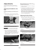
Adjusting the Bedknife to the
Reel
Bedknife to reel adjustment is accomplished by loosening
or tightening bedbar adjusting screws, located on top of
mower.
1. Position machine on a flat, level work surface. Make
sure reel contact is removed by turning bedbar adjusting
screws counterclockwise (Fig. 8).
1
Figure 8
1. Bedbar adjusting screw
2. Tilt mower on back to expose bedknife and reel.
Important Make sure nuts on back end of bedbar
adjusting screws are not resting on work surface (Fig. 4).
3. At one end of reel, insert a long strip of newspaper
between reel and bedknife (Fig. 9). While slowly
rotating reel forward, turn bedbar adjusting screw
clockwise (on same end of reel, one click at a time, until
paper is pinched lightly, when inserted from the front,
parallel to the bedknife. A slight drag will be noted as
the paper is pulled.
Figure 9
Note: Each time adjusting screw is rotated one click
clockwise, bedknife moves .0007 in. closer to reel. Do not
overtighten the adjusting screws.
4. Check for light contact at other end of reel using paper
and adjust as required.
5. After adjustment is accomplished, check to see if reel
can pinch paper when inserted from the front and cut
paper when inserted at a right angle to the bedknife
(Fig. 9). It should be possible to cut paper with
minimum contact between the bedknife and the reel
blades. Should excessive reel drag be evident it will be
either necessary to backlap or regrind the cutting unit to
achieve the sharp edges needed for precision cutting
(see Toro reel sharpening manual).
Adjusting the Rear Roller
1. Adjust rear roller brackets (Figs. 10 and 11) to low or
high position depending on desired height of cut range.
• Position the spacer above the sideplate mounting
flange (factory setting) when height of cut settings
range from 1/16 to 1/4” (Fig. 10).
1
2
3
Figure 10
1. Spacer
2. Roller bracket
3. Sideplate mounting flange
• Position the spacer below the sideplate mounting
flange when height of cut settings range from 1/8”
to 1” (Fig. 11).
2
3
1
Figure 11
1. Spacer
2. Roller bracket
3. Sideplate mounting flange