
Operator's Manual


6
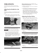
B. On right end of cutting unit, remove plastic plug
from bearing housing (Fig. 6).
C. Remove the 2 allen head screws securing the motor
mount to the right end of the cutting unit. Remove
the motor mount (Fig. 6).
1
3 2
Figure 6
1. Motor mount
2. Plastic plug
3. Allen head screw (2)
D. Remove the snap ring securing the drive coupler in
the reel tube (Fig. 7). Remove the drive coupler.
1
2
Figure 7
1. Snap ring 2. Drive coupler
E. Apply grease to the inside diameter of the drive
coupler. Install the drive coupler to the left end of
the cutting unit reel tube with a snap ring (Fig. 5).
F. Install the motor mount to the left end of the cutting
unit with the (2) allen head screws previously
removed (Fig. 6). Torque screws to 12–15 ft–lbs.
(16–20 N⋅m).
G. Install the counter weight to the right end of the
cutting unit with the screws previously removed.