
Service Manual


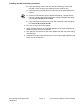


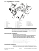

Table Of Contents
- Title Page
- Revision History
- Reader Comments
- Preface
- Table of Contents
- Chapter 1 : Safety
- Chapter 2 : Specifications and Maintenance
- Chapter 3 : Troubleshooting
- GEARS – The Systematic Approach to Defining, Diagnosing and Solving Problems
- Operator Advisories
- Dialogue Messages
- Machine Faults
- Using the InfoCenter Display for Troubleshooting
- Troubleshooting General Operation Problems
- Greensmaster 3360 (Model 04580)
- Greensmaster 3370 (Model 04590)
- Troubleshooting a Lithium-Ion Battery-Related Fault (Model 04590)
- Aftercut Appearance
- Grooming Performance
- Universal Groomer Problems (Optional)
- Battery Charger Error and Fault Codes (Model 04590)
- Chapter 4 : Engine (Model 04580)
- Chapter 5 : Electrical System
- General Information
- Electrical System Operation
- Traction Subsystem
- Steering Subsystem
- Lift/Lower Subsystem
- Cutting Unit Drive Subsystem
- 12 VDC System Components
- 48 VDC System Components
- 48V Battery Service Disconnect
- InfoCenter Display
- CAN bus Communications
- T1: Primary Controller
- SC8: Lithium-Ion Battery Controller (Model 04590)
- T6: Precharge Controller (Model 04590)
- Electrical System Quick Checks
- Adjustments
- Testing the Electrical Components
- Fuses
- CAN bus
- CAN bus Isolation Module
- InfoCenter Display
- T1: Primary Controller
- Starter/Generator (Model 04580)
- SC8: Lithium-Ion Battery Controller (Model 04590)
- T6: Precharge Controller (Model 04590)
- 48 VDC/12 VDC Converter (Model 04590)
- Front Traction Motor Controllers
- Front Traction Motor
- Rear Wheel Traction Motor (Optional 3WD)
- Steering Input Device
- Steering Motor
- Location ID Module
- Cutting Unit Motors
- Key Switch (Model 04580)
- Key Switch (Model 04590)
- Function Control Switch
- Light Switch (Optional)
- Seat Switch
- Brake Actuator
- Manual Parking Brake Switch
- Cutting Unit Lift/Lower Switches
- Lift/Lower Actuators
- Engine Oil Pressure Switch (Model 04580)
- Traction Pedal Position Sensor
- Steering Position Sensor
- Relays
- Contactors
- Diode Assemblies
- CAN bus Terminator Resistors
- Lead Acid Batteries (Model 04580)
- Lithium-Ion Batteries (Model 04590)
- Service and Repairs
- Chapter 6 : Chassis
- General Information
- Adjustments
- Service and Repairs
- Wheels and Tires
- Front Wheel Hubs
- Front Traction Gear Box
- Front Traction Gear Box Service
- Rear Wheel Hub (Standard)
- Rear Wheel Hub (Optional 3WD)
- Rear Wheel Gear Box (Optional 3WD)
- Traction Pedal Assembly
- Brake Assembly
- Rear Wheel Caster Fork
- Steering Housing
- Steering Arm Assembly
- Control Console
- Platform Assembly
- Operator’s Seat
- Frame Assembly
- Hood Assembly
- Cutting Unit Suspension Assembly
- Cutting Unit Suspension Crossarm Assembly
- Chapter 7 : DPA Cutting Units
- Chapter 8 : Universal Groomer (Optional)
- Appendix A: Foldout Drawings
- Electrical Drawing Designations
- Electrical Schematic – 3360
- Electrical Schematic – 3370
- Electrical Schematic – 3370 (continued)
- Wire Harness Drawing – 3360 (Serial number below 409000000)
- Wire Harness Diagram – 3360 (Serial number below 409000000)
- Wire Harness Diagram – 3360 (Serial number below 409000000) (continued)
- Wire Harness Drawing – 3360 (Serial number above 409000000)
- Wire Harness Diagram – 3360 (Serial number above 409000000)
- Wire Harness Diagram – 3360 (Serial number above 409000000) (continued)
- NO TITLE
- Wire Harness Drawing – 3370
- Wire Harness Diagram – 3370
- Wire Harness Diagram – 3370

ServicingtheGroomerReel(continued)
bladestoputthesharpestbladeedgeforward.Thebladesthatareroundedto
themidpointofthebladetipmustbereversedorreplacedforbestgroomer
performance.
g285716
Figure187
1.Groomerreelshaft
5.Roundededge
2.Groomerblade(40each)
6.Midpoint
3.Spacer(39each)
7.Centeredonshaft
4.Locknut(2each)
1.Parkthemachineonacleanandlevelsurface,lowerthecuttingunit,setthe
keyswitchtotheOFFpositionandremovethekeyfromthekeyswitch.
2.Removethegroomerreelfromthecuttingunit;refertoRemovingthe
GroomerReel(page8–14).
3.Removethelocknutfromeitherendofthegroomerreelshaft.
4.Removethebladesandfromthegroomershaft.Ifnecessary,remove
secondlocknutfromtheshaft.
5.Inspectandreplacewornordamagedcomponents.
6.Assemblethegroomerreelasfollows:
Note:Newlocknutshaveanadhesivepatchtopreventthelocknutfrom
loosening.Ifausedlocknutisbeinginstalled,applyamediumstrength
threadlocker(Loctite#242orequivalent)tothethreadsofthelocknut.
A.Installalocknutononeendofthegroomerreelshaft.
B.Installagroomerbladeagainstthelocknut.
C.Installtheremainingspacersandbladesinanalternatingmannermaking
surethatallbladesareseparatedbyaspacer.
D.Whenallthebladeshavebeeninstalled,installthesecondlocknutonto
theshaft.Centerthebladesandspacersontheshaftbyadjustingthe
locknuts.
E.Usethethroughholesinshafttopreventtheshaftfromrotatingand
tightenthesecondlocknutto42to48N∙m(31to35ft-lb).After
Greensmaster®eTriFlex3360and3370
Page8–15
UniversalGroomer(Optional):ServiceandRepairs
19239SLRevF