
Service Manual


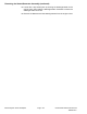


Table Of Contents
- Title Page
- Revision History
- Reader Comments
- Preface
- Table of Contents
- Chapter 1 : Safety
- Chapter 2 : Specifications and Maintenance
- Chapter 3 : Troubleshooting
- GEARS – The Systematic Approach to Defining, Diagnosing and Solving Problems
- Operator Advisories
- Dialogue Messages
- Machine Faults
- Using the InfoCenter Display for Troubleshooting
- Troubleshooting General Operation Problems
- Greensmaster 3360 (Model 04580)
- Greensmaster 3370 (Model 04590)
- Troubleshooting a Lithium-Ion Battery-Related Fault (Model 04590)
- Aftercut Appearance
- Grooming Performance
- Universal Groomer Problems (Optional)
- Battery Charger Error and Fault Codes (Model 04590)
- Chapter 4 : Engine (Model 04580)
- Chapter 5 : Electrical System
- General Information
- Electrical System Operation
- Traction Subsystem
- Steering Subsystem
- Lift/Lower Subsystem
- Cutting Unit Drive Subsystem
- 12 VDC System Components
- 48 VDC System Components
- 48V Battery Service Disconnect
- InfoCenter Display
- CAN bus Communications
- T1: Primary Controller
- SC8: Lithium-Ion Battery Controller (Model 04590)
- T6: Precharge Controller (Model 04590)
- Electrical System Quick Checks
- Adjustments
- Testing the Electrical Components
- Fuses
- CAN bus
- CAN bus Isolation Module
- InfoCenter Display
- T1: Primary Controller
- Starter/Generator (Model 04580)
- SC8: Lithium-Ion Battery Controller (Model 04590)
- T6: Precharge Controller (Model 04590)
- 48 VDC/12 VDC Converter (Model 04590)
- Front Traction Motor Controllers
- Front Traction Motor
- Rear Wheel Traction Motor (Optional 3WD)
- Steering Input Device
- Steering Motor
- Location ID Module
- Cutting Unit Motors
- Key Switch (Model 04580)
- Key Switch (Model 04590)
- Function Control Switch
- Light Switch (Optional)
- Seat Switch
- Brake Actuator
- Manual Parking Brake Switch
- Cutting Unit Lift/Lower Switches
- Lift/Lower Actuators
- Engine Oil Pressure Switch (Model 04580)
- Traction Pedal Position Sensor
- Steering Position Sensor
- Relays
- Contactors
- Diode Assemblies
- CAN bus Terminator Resistors
- Lead Acid Batteries (Model 04580)
- Lithium-Ion Batteries (Model 04590)
- Service and Repairs
- Chapter 6 : Chassis
- General Information
- Adjustments
- Service and Repairs
- Wheels and Tires
- Front Wheel Hubs
- Front Traction Gear Box
- Front Traction Gear Box Service
- Rear Wheel Hub (Standard)
- Rear Wheel Hub (Optional 3WD)
- Rear Wheel Gear Box (Optional 3WD)
- Traction Pedal Assembly
- Brake Assembly
- Rear Wheel Caster Fork
- Steering Housing
- Steering Arm Assembly
- Control Console
- Platform Assembly
- Operator’s Seat
- Frame Assembly
- Hood Assembly
- Cutting Unit Suspension Assembly
- Cutting Unit Suspension Crossarm Assembly
- Chapter 7 : DPA Cutting Units
- Chapter 8 : Universal Groomer (Optional)
- Appendix A: Foldout Drawings
- Electrical Drawing Designations
- Electrical Schematic – 3360
- Electrical Schematic – 3370
- Electrical Schematic – 3370 (continued)
- Wire Harness Drawing – 3360 (Serial number below 409000000)
- Wire Harness Diagram – 3360 (Serial number below 409000000)
- Wire Harness Diagram – 3360 (Serial number below 409000000) (continued)
- Wire Harness Drawing – 3360 (Serial number above 409000000)
- Wire Harness Diagram – 3360 (Serial number above 409000000)
- Wire Harness Diagram – 3360 (Serial number above 409000000) (continued)
- NO TITLE
- Wire Harness Drawing – 3370
- Wire Harness Diagram – 3370
- Wire Harness Diagram – 3370

DisassemblingtheStarter/Generator(continued)
3.Removetheaccesscover(item9)andthecovergasketfromthecontroller.
Discardthecovergasket.
4.Recordthepositionoftheconnectorsandthewireharnessesforassembly
purposes.Carefullyremovethestarter/generatorandcontrollerharness
connectorsfromthecontrolleropeningandunplugtheconnectors.
5.Removethethreeangeheadscrews(item11)thatsecurethe
starter/generatorstatorconductorstothecontrollerconnectors.
6.Removethefastenersthatsecurethecontrollertothestarter/generator
assembly.Liftthecontrollerfromthestarter/generator.Removeanddiscard
theO-ring(item20).
Note:Ifcontrollerdamageexists,controllerreplacementisnecessary.
Internalcontrollercomponentsarenotavailableseparately.Ifthe
starter/generatorcontrollerisreplaced,themachinesoftwaremustbe
updated;contactanAuthorizedToroDistributorforassistance.
7.Removethestarter/generatorfan:
A.Removetheangeheadscrewandthecollarfromthestarter/generator
shaft.
B.T opreventdamagetothestarter/generatorshaftthreads,installaplain
washerinthecenterholeofthestarter/generatorfantoprotectthe
starter/generatorshaftthreadsbeforeremovingthestarter/generatorfan.
g288972
Figure103
1.Generatorshaft4.Collar
2.Generatorfan5.3/8-16x1inchcapscrew
3.Plainwasher
6.Screw(3each)
C.Installthecollaronthestarter/generatorfanwiththreeoftherotating
screenscrewspreviouslyremoved.
D.Threada3/8-16x1capscrewintothecollar.
E.Supportfantopreventitfromfallingandtightenthecapscrewtoremove
thefan.
F.Locateandretrievethewoodruffkey.
8.Removethestarter/generatorpulley.Locateandretrievethesquarekey.
ElectricalSystem:ServiceandRepairs
Page5–126
Greensmaster®eTriFlex3360and3370
19239SLRevF