
Service Manual
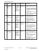


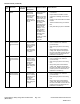


Table Of Contents
- Title Page
- Revision History
- Reader Comments
- Preface
- Chapter 1 : Safety
- Chapter 2 : Specifications and Maintenance
- Chapter 3 : Troubleshooting
- GEARS – The Systematic Approach to Defining, Diagnosing and Solving Problems
- Operator Advisories
- Dialogue Messages
- Machine Faults
- Using the InfoCenter Display for Troubleshooting
- Troubleshooting General Operation Problems
- Greensmaster 3360 (Model 04580)
- Greensmaster 3370 (Model 04590)
- Troubleshooting a Lithium-Ion Battery-Related Fault (Model 04590)
- Aftercut Appearance
- Grooming Performance
- Universal Groomer Problems (Optional)
- Battery Charger Error and Fault Codes (Model 04590)
- Chapter 4 : Engine (Model 04580)
- Chapter 5 : Electrical System
- General Information
- Electrical System Operation
- Traction Subsystem
- Steering Subsystem
- Lift/Lower Subsystem
- Cutting Unit Drive Subsystem
- 12 VDC System Components
- 48 VDC System Components
- 48V Battery Service Disconnect
- InfoCenter Display
- CAN bus Communications
- T1: Primary Controller
- SC8: Lithium-Ion Battery Controller (Model 04590)
- T6: Precharge Controller (Model 04590)
- Electrical System Quick Checks
- Adjustments
- Testing the Electrical Components
- Fuses
- CAN bus
- CAN bus Isolation Module
- InfoCenter Display
- T1: Primary Controller
- Starter/Generator (Model 04580)
- SC8: Lithium-Ion Battery Controller (Model 04590)
- T6: Precharge Controller (Model 04590)
- 48 VDC/12 VDC Converter (Model 04590)
- Front Traction Motor Controllers
- Front Traction Motor
- Rear Wheel Traction Motor (Optional 3WD)
- Steering Input Device
- Steering Motor
- Location ID Module
- Cutting Unit Motors
- Key Switch (Model 04580)
- Key Switch (Model 04590)
- Function Control Switch
- Light Switch (Optional)
- Seat Switch
- Brake Actuator
- Manual Parking Brake Switch
- Cutting Unit Lift/Lower Switches
- Lift/Lower Actuators
- Engine Oil Pressure Switch (Model 04580)
- Traction Pedal Position Sensor
- Steering Position Sensor
- Relays
- Contactors
- Diode Assemblies
- CAN bus Terminator Resistors
- Lead Acid Batteries (Model 04580)
- Lithium-Ion Batteries (Model 04590)
- Service and Repairs
- Chapter 6 : Chassis
- General Information
- Adjustments
- Service and Repairs
- Wheels and Tires
- Front Wheel Hubs
- Front Traction Gear Box
- Front Traction Gear Box Service
- Rear Wheel Hub (Standard)
- Rear Wheel Hub (Optional 3WD)
- Rear Wheel Gear Box (Optional 3WD)
- Traction Pedal Assembly
- Brake Assembly
- Rear Wheel Caster Fork
- Steering Housing
- Steering Arm Assembly
- Control Console
- Platform Assembly
- Operator’s Seat
- Frame Assembly
- Hood Assembly
- Cutting Unit Suspension Assembly
- Cutting Unit Suspension Crossarm Assembly
- Chapter 7 : DPA Cutting Units
- Chapter 8 : Universal Groomer (Optional)
- Appendix A: Foldout Drawings
- Electrical Drawing Designations
- Electrical Schematic – 3360
- Electrical Schematic – 3370
- Electrical Schematic – 3370 (continued)
- Wire Harness Drawing – 3360
- Wire Harness Diagram – 3360
- Wire Harness Diagram – 3360 (continued)
- Wire Harness Drawing – 3370
- Wire Harness Diagram – 3370
- Wire Harness Diagram – 3370 (continued)

MachineFaults(continued)
Fault
ID
FaultTitle
Controller(s)
Affected
Fault
Condition/Circuit
Description
AdditionalNotes
ServiceActions
U1012
ControllerLogic
Voltage-Low
T1,T6
Thisfaultis
reportedwhen
the12Vlogic
circuitvoltageis
below8.8V(T1),
or48Vlogic
circuitvoltageis
below32V(T6).
PTOisdisabled.1.IfthefaultisgeneratedbytheT1
primarycontroller:
A.ChecktheoutputoftheDC-to-DC
converterontheInfoCenter.
B.Measurethelogicvoltageatthe
DC-to-DCconverter.
C.Measurethelogicvoltageatthe
T1primarycontroller.
D.Testthe48VDC/12VDC
converter.
E.SwaptheT1:Primarycontroller
withaknown-goodunit(contact
anAuthorizedT oroDistributorfor
assistance).
2.IfthefaultisgeneratedbytheT6
prechargecontroller:
A.Checkthepowersupply(fused)
andgroundtotheT6precharge
controller.
B.ReplacetheT6:precharge
controller(contactanAuthorized
ToroDistributorforassistance).
U1025
TEC(T1
Primary
controller)Fuse
5Failure
T1
Thisfaultis
reportedwhen
thefusehas
failedforoutputs
13–16onthe
T1:Primary
controller.
ConnectorP01,
pin38,outputwill
notfunction.
1.Testthe7.5Aminibladestylefusein
the12Vfuseholder(undertheright
sidecover).
2.Checkthefuseholdercircuitwiring
andconnector(P68).
U110C
ModelNumber
Unknown
T1
Thisfaultis
reportedwhen
themodel
numbernot
recognized.
Engineis
disabled.
Updatemachinesoftware(contactan
AuthorizedT oroDistributorforassistance).
U1117
SourceAddress
Contention
Fault
T1
Thisfaultis
reportedwhen
theT1primary
controller
receivesa
message
fromanother
controlleronthe
CANbususing
thesamesource
address.
Machineis
disabled.
Note:Most
often,thisfault
iscausedby
installinga
controllerthat
wasprogrammed
whileitwas
installedin
anothermachine.
Updatemachinesoftware(contactan
AuthorizedT oroDistributorforassistance).
U111F
SourceID-CU
MotorIDOutof
Range
T1
Thisfaultis
reportedwhen
multiplecutting
unitmotorsare
reportingthe
samenodeIDor
address.
PTOisdisabled.1.Inspectforloosewireorconnectorat
thecuttingunitmotorsandtheCAN
IDmodule.
2.TesttheresistanceofthemotorIDpin
(pin2ofthe4-pinmotorconnector).It
shouldbe18kto20kohm.
3.TesttheCANIDmodule.
Greensmaster®eTriFlex3360and3370
Page3–35
Troubleshooting:BatteryChargerErrorand
FaultCodes(Model04590)
19239SLRevE