
Service Manual


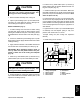


Table Of Contents
- Title Page
- Revision History
- Reader Comments
- Preface
- Table Of Contents
- 1 - Safety
- 2 - Product Records and Maintenance
- 3 - Gasoline Engine
- 4 - Diesel Engine
- 5 - Hydraulic System
- Table of Contents
- Specifications
- General Information
- Operator's Manuals
- Check Hydraulic Fluid Level
- Pushing Traction Unit
- Relieving Hydraulic System Pressure
- Opening Electrical Circuit to Cutting Units
- Traction Circuit Component Failure
- Hydraulic Hoses
- Hydraulic Hose and Tube Installation (O-Ring Face Seal Fitting)
- Hydraulic Fitting Installation (SAE Straight Thread O-Ring Fitting into Component Port)
- Hydraulic Schematic
- Hydraulic Flow Diagrams
- Special Tools
- Troubleshooting
- Testing
- Charge Relief Valve Pressure Test (Using Pressure Gauge)
- Piston (Traction) Pump Flow Test (Using Tester with Flowmeter and Pressure Gauge)
- Wheel Motor Efficiency Test (Using Tester with Flowmeter and Pressure Gauge)
- Steering/Lift Relief Valve Pressure Test (Using Pressure Gauge)
- Lower Cutting Units Relief Valve (RV) Pressure Test (Using Pressure Gauge)
- Steering/Lift Circuit Gear Pump Flow Test (Using Tester with Flowmeter and Pressure Gauge)
- Power Steering Valve Test
- Adjustments
- Service and Repairs
- General Precautions for Removing and Installing Hydraulic System Components
- Flush Hydraulic System
- Filtering Closed-Loop Traction Circuit
- Hydraulic System Start-up
- Gear Pump
- Gear Pump Service
- Piston (Traction) Pump Neutral Assembly
- Piston (Traction) Pump
- Piston (Traction) Pump Service
- Piston Pump Crush Ring Replacement
- Front Wheel Motors
- Rear Wheel Motor (Optional 3WD)
- Wheel Motor Service
- Lift Cylinders
- Lift Cylinder Service
- Lift Control Manifold
- Lift Control Manifold Service
- Control Manifold Cartridge Valve Service
- Power Steering Valve
- Power Steering Valve Service
- Steering Cylinder
- Steering Cylinder Service
- Hydraulic Reservoir
- Leak Detector Tank (Machines Equipped with Optional Turf GuardianTM Leak Detector System)
- Leak Detector Solenoid Valve Assembly (Machines Equipped with Optional Turf GuardianTM Leak Detector System)
- 6 - Electrical System
- Table of Contents
- General Information
- Electrical System Operation
- Turf GuardianTM Leak Detector System Operation (Optional Kit)
- Special Tools
- InfoCenter Display (Serial Number Above 312000000)
- Troubleshooting
- Electrical System Quick Checks
- Adjustments
- Component Testing
- Ignition Switch (Serial Number Below 312000000)
- Ignition Switch (Serial Number Above 312000000)
- Engine Oil Pressure Indicator Light (Greensmaster 3320 with Serial Number Below 312000000)
- Indicator Lights (Greensmaster 3420 with Serial Number Below 312000000)
- Fuse Block (Greensmaster 3320)
- Fuse Block (Greensmaster 3420 with Serial Number Below 312000000)
- Fuse Block (Greensmaster 3420 with Serial Number Above 312000000)
- Electric Reel Drive System (48 Volt DC) Fuses
- Fusible Links
- Hour Meter
- Seat Switch
- Neutral and Mow Switches
- Parking Brake Switch
- Joystick Raise and Lower Switches
- Backlap Switch
- Electric Reel Contactor
- Reel Speed Potentiometer (Serial Number Below 312000000)
- Toro Electronic Controller (TEC)
- Hydraulic Solenoid Valve Coils
- Main Power, Electric Cutting Reels Enable, Charge Circuit (Greensmaster 3320), Glow (Greensmaster 3420) and Fan (Greensmas...
- Kill (Greensmaster 3320) and Start (Greensmaster 3420) Relays
- CAN-bus Termination Resistors
- Electric Reel Circuit Protection Diode
- Location ID Module
- Cutting Reel Motors
- Starter Solenoid (Greensmaster 3320)
- Fuel Pump (Greensmaster 3420)
- Fuel Solenoid (Greensmaster 3420)
- Temperature Sender (Greensmaster 3420)
- Diode Assembly (Greensmaster 3420)
- Turf GuardianTM Leak Detector Oil Level Sensor (If Equipped)
- Turf GuardianTM Leak Detector Alarm (If Equipped)
- Service and Repairs
- Verify Interlock System Operation
- 12 Volt Battery Care
- 12 Volt Battery Storage
- 12 Volt Battery Service
- Electric Reel Drive System (48 Volt DC) Battery Pack Service
- Generator Drive Belt (Greensmaster 3320)
- Generator Drive Belt (Greensmaster 3420)
- Generator Assembly (Greensmaster 3320)
- Generator Assembly (Greensmaster 3420)
- Generator Assembly Service
- Cutting Reel Motor
- Cutting Reel Motor Service
- 7 - Chassis
- 8 - DPA Cutting Units
- 9 - Groomer
- Table of Contents
- Specifications
- General Information
- Troubleshooting
- Adjustments
- Service and Repairs
- Groomer Belt Replacement (Forward Rotating Groomer Drive)
- Groomer Cover (Counter Rotating Groomer Drive)
- Grooming Reel (Forward Rotating Groomer Drive)
- Grooming Reel (Counter Rotating Groomer Drive)
- Grooming Reel Service
- Grooming Reel Bearing Replacement
- Idler Assembly (Forward Rotating Groomer Drive)
- Idler Assembly (Counter Rotating Groomer Drive)
- Lift Arm Assembly
- Groomer Brush
- 10 - Universal Groomer (Optional)
- 11 - Foldout Drawings
- Table of Contents
- Hydraulic Schematic
- Electrical Schematic GR3320
- Electrical Schematic GR3320
- Greensmaster 3320Electrical Schematic(Serial Numbers 314000001 to 316000000)
- Greensmaster 3320Electrical Schematic(Serial Numbers 316000001 to 403410000)
- Greensmaster 3320Electrical Schematic(Serial Numbers above 403410001)
- Electrical Schematic GR3420
- Electrical Schematic GR3420
- Greensmaster 3420Electrical Schematic(Serial Numbers 314003001 to 316000000)
- Greensmaster 3420Electrical Schematic(Serial Numbers 316000001 to 403420000)
- Greensmaster 3420Electrical Schematic(Serial Numbers above 403420001)
- E−Reels Electrical Schematic
- E−Reels Electrical Schematic
- Wire Harness Drawing GR3320
- Wire Harness Diagram GR3320
- Wire Harness Drawing GR3320
- Wire Harness Diagram GR3320
- Wire Harness DrawingGreensmaster 3320(Serial Numbers 316000001 to 403410000)
- Wire Harness DrawingGreensmaster 3320(Serial Numbers 316000001 to 403410000)
- Wire Harness DrawingGreensmaster 3320(Serial Numbers 403410001 to 406000000)
- Wire Harness DiagramGreensmaster 3320(Serial Numbers 403410001 to 406000000)
- Wire Harness DrawingGreensmaster 3320(Serial Numbers above 406000001)
- Wire Harness DiagramGreensmaster 3320(Serial Numbers above 406000001)
- Wire Harness Drawing GR3420
- Wire Harness Diagram GR3420
- Wire Harness Drawing GR3420
- Wire Harness Diagram GR3420
- Wire Harness DrawingGreensmaster 3420(Serial Numbers 314000001 to 316000000)
- Wire Harness DiagramGreensmaster 3420(Serial Numbers 314000001 to 316000000)
- Wire Harness DrawingGreensmaster 3420(Serial Numbers 316000001 to 316000500)
- Wire Harness DiagramGreensmaster 3420(Serial Numbers 316000001 to 316000500)
- Wire Harness DrawingGreensmaster 3420(Serial Numbers 316000501 to 403420000)
- Wire Harness DiagramGreensmaster 3420(Serial Numbers 316000501 to 403420000)
- Wire Harness DrawingGreensmaster 3420(Serial Numbers 403420000 to 405700000)
- Wire Harness DiagramGreensmaster 3420(Serial Numbers 403420000 to 405700000)
- Wire Harness DrawingGreensmaster 3420(Serial Numbers above 405700001)
- Wire Harness DiagramGreensmaster 3420(Serial Numbers above 405700001)
- E−Reels Wire Harness Drawing
- E−Reels Wire Harness Diagram
- E−Reels Wire Harness Drawing
- E−Reels Wire Harness Diagram
- E−Reels Wire Harness Drawing
- E−Reels Wire Harness Diagram

Greensmaster 3320/3420
DPA Cutting Units
Page 8 − 15
CAUTION
Contact with the reel, bedknife or other cutting
unit parts can result in personal injury. Use
heavy gloves when handling the bedbar.
7. Remove bedbar assembly from cutting unit.
8. Inspect nylon bushings (item 15) and rubber bush-
ings (item 14) in side plates for wear or damage. Re-
move bushings and replace if necessary.
Bedbar Installation (Fig. 17)
1. If rubber bushing was removed from either cutting
unit side plate, apply grease to outside surface of new
bushing and install into side plate. The bushing should
be installed flush with the inside of the side plate (Fig.
18).
2. If removed, install the nylon bushings (item 15) with
flange facing outward. Apply antiseize lubricant to inside
of flange bushing.
3. Apply antiseize lubricant to the bedbar threads and
the shoulder area of each bedbar pivot bolt (Fig. 18).
IMPORTANT: When installing washers (items 16
and 17), make sure that plastic washers are posi-
tioned on either side of the cutting unit sideplate
(Fig. 18).
4. Slide one (1) metal washer (item 17) and then one (1)
plastic washer (item 16) onto each bedbar pivot bolt.
CAUTION
Contact with the reel, bedknife or other cutting
unit parts can result in personal injury. Use
heavy gloves when handling the bedbar.
5. Position bedbar into cutting unit. Make sure that the
top of each bedbar arm is between washer (item 11) and
adjuster screw flange (item 4).
6. Position one (1) metal washer (item 17) and one (1)
plastic washer (item 16) between bedbar and each cut-
ting unit side plate (Fig. 18).
7. Install the bedbar pivot bolt assemblies. Make sure
that plastic washers are not caught on the threads of the
pivot bolts. Torque each bedbar pivot bolt from 190 to
240 in−lb (22 to 27 N−m).
8. Tighten both lock nuts (item 10) until outside wash-
ers do not have any endplay but still can be rotated. Do
not over tighten the lock nuts as this can distort the side
plates and affect reel bearing adjustment. When the lock
nut is correctly tightened, there may be a gap at the in-
side washers.
9. Tighten the lock nut (item 13) on each bedbar adjust-
er assembly until the adjuster spring is fully com-
pressed, then loosen lock nut 1/2 turn.
10.Adjust cutting unit (see Cutting Unit Operator’s
Manual).
11.Install cutting unit to machine.
ÇÇÇÇ
ÇÇÇÇ
ÇÇÇÇ
ÇÇÇÇ
ÇÇÇÇ
1. Cutting unit sideplate
2. Rubber bushing
3. Nylon bushing
4. Plastic washer
5. Metal washer
6. Bedbar
7. Bedbar pivot bolt
8. Lock nut
Figure 18
1
2
3
4
6
7
8
5
4
Antiseize
Lubricant
5
DPA Cutting
Units