
Service Manual


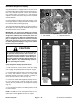
Table Of Contents
- Title Page
- Revision History
- Reader Comments
- Preface
- Table Of Contents
- 1 - Safety
- 2 - Product Records and Maintenance
- 3 - Gasoline Engine
- 4 - Diesel Engine
- 5 - Hydraulic System
- Table of Contents
- Specifications
- General Information
- Operator's Manuals
- Check Hydraulic Fluid Level
- Pushing Traction Unit
- Relieving Hydraulic System Pressure
- Opening Electrical Circuit to Cutting Units
- Traction Circuit Component Failure
- Hydraulic Hoses
- Hydraulic Hose and Tube Installation (O-Ring Face Seal Fitting)
- Hydraulic Fitting Installation (SAE Straight Thread O-Ring Fitting into Component Port)
- Hydraulic Schematic
- Hydraulic Flow Diagrams
- Special Tools
- Troubleshooting
- Testing
- Charge Relief Valve Pressure Test (Using Pressure Gauge)
- Piston (Traction) Pump Flow Test (Using Tester with Flowmeter and Pressure Gauge)
- Wheel Motor Efficiency Test (Using Tester with Flowmeter and Pressure Gauge)
- Steering/Lift Relief Valve Pressure Test (Using Pressure Gauge)
- Lower Cutting Units Relief Valve (RV) Pressure Test (Using Pressure Gauge)
- Steering/Lift Circuit Gear Pump Flow Test (Using Tester with Flowmeter and Pressure Gauge)
- Power Steering Valve Test
- Adjustments
- Service and Repairs
- General Precautions for Removing and Installing Hydraulic System Components
- Flush Hydraulic System
- Filtering Closed-Loop Traction Circuit
- Hydraulic System Start-up
- Gear Pump
- Gear Pump Service
- Piston (Traction) Pump Neutral Assembly
- Piston (Traction) Pump
- Piston (Traction) Pump Service
- Piston Pump Crush Ring Replacement
- Front Wheel Motors
- Rear Wheel Motor (Optional 3WD)
- Wheel Motor Service
- Lift Cylinders
- Lift Cylinder Service
- Lift Control Manifold
- Lift Control Manifold Service
- Control Manifold Cartridge Valve Service
- Power Steering Valve
- Power Steering Valve Service
- Steering Cylinder
- Steering Cylinder Service
- Hydraulic Reservoir
- Leak Detector Tank (Machines Equipped with Optional Turf GuardianTM Leak Detector System)
- Leak Detector Solenoid Valve Assembly (Machines Equipped with Optional Turf GuardianTM Leak Detector System)
- 6 - Electrical System
- Table of Contents
- General Information
- Electrical System Operation
- Turf GuardianTM Leak Detector System Operation (Optional Kit)
- Special Tools
- InfoCenter Display (Serial Number Above 312000000)
- Troubleshooting
- Electrical System Quick Checks
- Adjustments
- Component Testing
- Ignition Switch (Serial Number Below 312000000)
- Ignition Switch (Serial Number Above 312000000)
- Engine Oil Pressure Indicator Light (Greensmaster 3320 with Serial Number Below 312000000)
- Indicator Lights (Greensmaster 3420 with Serial Number Below 312000000)
- Fuse Block (Greensmaster 3320)
- Fuse Block (Greensmaster 3420 with Serial Number Below 312000000)
- Fuse Block (Greensmaster 3420 with Serial Number Above 312000000)
- Electric Reel Drive System (48 Volt DC) Fuses
- Fusible Links
- Hour Meter
- Seat Switch
- Neutral and Mow Switches
- Parking Brake Switch
- Joystick Raise and Lower Switches
- Backlap Switch
- Electric Reel Contactor
- Reel Speed Potentiometer (Serial Number Below 312000000)
- Toro Electronic Controller (TEC)
- Hydraulic Solenoid Valve Coils
- Main Power, Electric Cutting Reels Enable, Charge Circuit (Greensmaster 3320), Glow (Greensmaster 3420) and Fan (Greensmas...
- Kill (Greensmaster 3320) and Start (Greensmaster 3420) Relays
- CAN-bus Termination Resistors
- Electric Reel Circuit Protection Diode
- Location ID Module
- Cutting Reel Motors
- Starter Solenoid (Greensmaster 3320)
- Fuel Pump (Greensmaster 3420)
- Fuel Solenoid (Greensmaster 3420)
- Temperature Sender (Greensmaster 3420)
- Diode Assembly (Greensmaster 3420)
- Turf GuardianTM Leak Detector Oil Level Sensor (If Equipped)
- Turf GuardianTM Leak Detector Alarm (If Equipped)
- Service and Repairs
- Verify Interlock System Operation
- 12 Volt Battery Care
- 12 Volt Battery Storage
- 12 Volt Battery Service
- Electric Reel Drive System (48 Volt DC) Battery Pack Service
- Generator Drive Belt (Greensmaster 3320)
- Generator Drive Belt (Greensmaster 3420)
- Generator Assembly (Greensmaster 3320)
- Generator Assembly (Greensmaster 3420)
- Generator Assembly Service
- Cutting Reel Motor
- Cutting Reel Motor Service
- 7 - Chassis
- 8 - DPA Cutting Units
- 9 - Groomer
- Table of Contents
- Specifications
- General Information
- Troubleshooting
- Adjustments
- Service and Repairs
- Groomer Belt Replacement (Forward Rotating Groomer Drive)
- Groomer Cover (Counter Rotating Groomer Drive)
- Grooming Reel (Forward Rotating Groomer Drive)
- Grooming Reel (Counter Rotating Groomer Drive)
- Grooming Reel Service
- Grooming Reel Bearing Replacement
- Idler Assembly (Forward Rotating Groomer Drive)
- Idler Assembly (Counter Rotating Groomer Drive)
- Lift Arm Assembly
- Groomer Brush
- 10 - Universal Groomer (Optional)
- 11 - Foldout Drawings
- Table of Contents
- Hydraulic Schematic
- Electrical Schematic GR3320
- Electrical Schematic GR3320
- Greensmaster 3320Electrical Schematic(Serial Numbers 314000001 to 316000000)
- Greensmaster 3320Electrical Schematic(Serial Numbers 316000001 to 403410000)
- Greensmaster 3320Electrical Schematic(Serial Numbers above 403410001)
- Electrical Schematic GR3420
- Electrical Schematic GR3420
- Greensmaster 3420Electrical Schematic(Serial Numbers 314003001 to 316000000)
- Greensmaster 3420Electrical Schematic(Serial Numbers 316000001 to 403420000)
- Greensmaster 3420Electrical Schematic(Serial Numbers above 403420001)
- E−Reels Electrical Schematic
- E−Reels Electrical Schematic
- Wire Harness Drawing GR3320
- Wire Harness Diagram GR3320
- Wire Harness Drawing GR3320
- Wire Harness Diagram GR3320
- Wire Harness DrawingGreensmaster 3320(Serial Numbers 316000001 to 403410000)
- Wire Harness DrawingGreensmaster 3320(Serial Numbers 316000001 to 403410000)
- Wire Harness DrawingGreensmaster 3320(Serial Numbers 403410001 to 406000000)
- Wire Harness DiagramGreensmaster 3320(Serial Numbers 403410001 to 406000000)
- Wire Harness DrawingGreensmaster 3320(Serial Numbers above 406000001)
- Wire Harness DiagramGreensmaster 3320(Serial Numbers above 406000001)
- Wire Harness Drawing GR3420
- Wire Harness Diagram GR3420
- Wire Harness Drawing GR3420
- Wire Harness Diagram GR3420
- Wire Harness DrawingGreensmaster 3420(Serial Numbers 314000001 to 316000000)
- Wire Harness DiagramGreensmaster 3420(Serial Numbers 314000001 to 316000000)
- Wire Harness DrawingGreensmaster 3420(Serial Numbers 316000001 to 316000500)
- Wire Harness DiagramGreensmaster 3420(Serial Numbers 316000001 to 316000500)
- Wire Harness DrawingGreensmaster 3420(Serial Numbers 316000501 to 403420000)
- Wire Harness DiagramGreensmaster 3420(Serial Numbers 316000501 to 403420000)
- Wire Harness DrawingGreensmaster 3420(Serial Numbers 403420000 to 405700000)
- Wire Harness DiagramGreensmaster 3420(Serial Numbers 403420000 to 405700000)
- Wire Harness DrawingGreensmaster 3420(Serial Numbers above 405700001)
- Wire Harness DiagramGreensmaster 3420(Serial Numbers above 405700001)
- E−Reels Wire Harness Drawing
- E−Reels Wire Harness Diagram
- E−Reels Wire Harness Drawing
- E−Reels Wire Harness Diagram
- E−Reels Wire Harness Drawing
- E−Reels Wire Harness Diagram

Greensmaster 3320/3420 Page 6 − 21 Electrical System
Retrieving Fault Codes
All machine fault codes are retained in the TEC control-
ler memory. The three (3) most recent fault codes that
have occurred within the last forty (40) hours of opera-
tion can be retrieved using the diagnostic light. To re-
trieve these fault codes from the controller memory,
perform the following switch sequence:
1. Operator seat should be UNOCCUPIED.
2. Place functional control lever in the TRANSPORT
position.
3. Make sure that backlap switch is in the MOW posi-
tion.
4. Move and hold joystick in the RAISE position.
5. Turn ignition switch to the RUN position.
6. Monitor the diagnostic light for fault code(s).
NOTE: Once the diagnostic light begins to display fault
codes, the joystick can be released.
Fault codes displayed by the diagnostic light consist of
two (2) numbers. The first number is from one (1) to
twelve (12) and the second number is from one (1) to
nine (9). There will be a one (1) second pause between
the first and second number of a code. Up to three (3)
fault codes retained in controller memory will be dis-
played by the diagnostic light in order from the most re-
cent fault to the oldest fault. If there are multiple faults in
controller memory, there will be a three (3) second
pause between codes. The fault codes will continually
repeat after a five (5) second pause until the ignition key
is turned off. See Fault Codes in this section to identify
faults that have occurred with a machine.
If there are no faults that have occurred within the last
forty (40) hours of operation, the diagnostic light will
flash continuously after performing the above fault re-
trieval switch sequence.
If a fault code is not retrieved from the controller memory
within forty (40) hours of machine operating time, the
fault cannot be retrieved from controller memory using
this procedure. If necessary, contact your Toro distribu-
tor to retrieve older fault codes.
Clearing Fault Codes
After the three (3) most recent fault codes have been re-
trieved, clearing of those faults can be completed using
the following switch sequence:
1. Place machine switches in fault retrieval mode (see
above). The diagnostic light should be displaying the
fault codes.
2. Operator seat should remain UNOCCUPIED.
3. Move backlap switch to the BACKLAP position.
4. Move joystick to the RAISE position.
5. Monitor the diagnostic light for continuous flashing
indicating that faults have been cleared from the control-
ler memory.
Electrical
System