
Service Manual


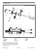
Table Of Contents
- Title Page
- Revision History
- Reader Comments
- Preface
- Table Of Contents
- 1 - Safety
- 2 - Product Records and Maintenance
- 3 - Gasoline Engine
- 4 - Diesel Engine
- 5 - Hydraulic System
- Table of Contents
- Specifications
- General Information
- Operator's Manuals
- Check Hydraulic Fluid Level
- Pushing Traction Unit
- Relieving Hydraulic System Pressure
- Opening Electrical Circuit to Cutting Units
- Traction Circuit Component Failure
- Hydraulic Hoses
- Hydraulic Hose and Tube Installation (O-Ring Face Seal Fitting)
- Hydraulic Fitting Installation (SAE Straight Thread O-Ring Fitting into Component Port)
- Hydraulic Schematic
- Hydraulic Flow Diagrams
- Special Tools
- Troubleshooting
- Testing
- Charge Relief Valve Pressure Test (Using Pressure Gauge)
- Piston (Traction) Pump Flow Test (Using Tester with Flowmeter and Pressure Gauge)
- Wheel Motor Efficiency Test (Using Tester with Flowmeter and Pressure Gauge)
- Steering/Lift Relief Valve Pressure Test (Using Pressure Gauge)
- Lower Cutting Units Relief Valve (RV) Pressure Test (Using Pressure Gauge)
- Steering/Lift Circuit Gear Pump Flow Test (Using Tester with Flowmeter and Pressure Gauge)
- Power Steering Valve Test
- Adjustments
- Service and Repairs
- General Precautions for Removing and Installing Hydraulic System Components
- Flush Hydraulic System
- Filtering Closed-Loop Traction Circuit
- Hydraulic System Start-up
- Gear Pump
- Gear Pump Service
- Piston (Traction) Pump Neutral Assembly
- Piston (Traction) Pump
- Piston (Traction) Pump Service
- Piston Pump Crush Ring Replacement
- Front Wheel Motors
- Rear Wheel Motor (Optional 3WD)
- Wheel Motor Service
- Lift Cylinders
- Lift Cylinder Service
- Lift Control Manifold
- Lift Control Manifold Service
- Control Manifold Cartridge Valve Service
- Power Steering Valve
- Power Steering Valve Service
- Steering Cylinder
- Steering Cylinder Service
- Hydraulic Reservoir
- Leak Detector Tank (Machines Equipped with Optional Turf GuardianTM Leak Detector System)
- Leak Detector Solenoid Valve Assembly (Machines Equipped with Optional Turf GuardianTM Leak Detector System)
- 6 - Electrical System
- Table of Contents
- General Information
- Electrical System Operation
- Turf GuardianTM Leak Detector System Operation (Optional Kit)
- Special Tools
- InfoCenter Display (Serial Number Above 312000000)
- Troubleshooting
- Electrical System Quick Checks
- Adjustments
- Component Testing
- Ignition Switch (Serial Number Below 312000000)
- Ignition Switch (Serial Number Above 312000000)
- Engine Oil Pressure Indicator Light (Greensmaster 3320 with Serial Number Below 312000000)
- Indicator Lights (Greensmaster 3420 with Serial Number Below 312000000)
- Fuse Block (Greensmaster 3320)
- Fuse Block (Greensmaster 3420 with Serial Number Below 312000000)
- Fuse Block (Greensmaster 3420 with Serial Number Above 312000000)
- Electric Reel Drive System (48 Volt DC) Fuses
- Fusible Links
- Hour Meter
- Seat Switch
- Neutral and Mow Switches
- Parking Brake Switch
- Joystick Raise and Lower Switches
- Backlap Switch
- Electric Reel Contactor
- Reel Speed Potentiometer (Serial Number Below 312000000)
- Toro Electronic Controller (TEC)
- Hydraulic Solenoid Valve Coils
- Main Power, Electric Cutting Reels Enable, Charge Circuit (Greensmaster 3320), Glow (Greensmaster 3420) and Fan (Greensmas...
- Kill (Greensmaster 3320) and Start (Greensmaster 3420) Relays
- CAN-bus Termination Resistors
- Electric Reel Circuit Protection Diode
- Location ID Module
- Cutting Reel Motors
- Starter Solenoid (Greensmaster 3320)
- Fuel Pump (Greensmaster 3420)
- Fuel Solenoid (Greensmaster 3420)
- Temperature Sender (Greensmaster 3420)
- Diode Assembly (Greensmaster 3420)
- Turf GuardianTM Leak Detector Oil Level Sensor (If Equipped)
- Turf GuardianTM Leak Detector Alarm (If Equipped)
- Service and Repairs
- Verify Interlock System Operation
- 12 Volt Battery Care
- 12 Volt Battery Storage
- 12 Volt Battery Service
- Electric Reel Drive System (48 Volt DC) Battery Pack Service
- Generator Drive Belt (Greensmaster 3320)
- Generator Drive Belt (Greensmaster 3420)
- Generator Assembly (Greensmaster 3320)
- Generator Assembly (Greensmaster 3420)
- Generator Assembly Service
- Cutting Reel Motor
- Cutting Reel Motor Service
- 7 - Chassis
- 8 - DPA Cutting Units
- 9 - Groomer
- Table of Contents
- Specifications
- General Information
- Troubleshooting
- Adjustments
- Service and Repairs
- Groomer Belt Replacement (Forward Rotating Groomer Drive)
- Groomer Cover (Counter Rotating Groomer Drive)
- Grooming Reel (Forward Rotating Groomer Drive)
- Grooming Reel (Counter Rotating Groomer Drive)
- Grooming Reel Service
- Grooming Reel Bearing Replacement
- Idler Assembly (Forward Rotating Groomer Drive)
- Idler Assembly (Counter Rotating Groomer Drive)
- Lift Arm Assembly
- Groomer Brush
- 10 - Universal Groomer (Optional)
- 11 - Foldout Drawings
- Table of Contents
- Hydraulic Schematic
- Electrical Schematic GR3320
- Electrical Schematic GR3320
- Greensmaster 3320Electrical Schematic(Serial Numbers 314000001 to 316000000)
- Greensmaster 3320Electrical Schematic(Serial Numbers 316000001 to 403410000)
- Greensmaster 3320Electrical Schematic(Serial Numbers above 403410001)
- Electrical Schematic GR3420
- Electrical Schematic GR3420
- Greensmaster 3420Electrical Schematic(Serial Numbers 314003001 to 316000000)
- Greensmaster 3420Electrical Schematic(Serial Numbers 316000001 to 403420000)
- Greensmaster 3420Electrical Schematic(Serial Numbers above 403420001)
- E−Reels Electrical Schematic
- E−Reels Electrical Schematic
- Wire Harness Drawing GR3320
- Wire Harness Diagram GR3320
- Wire Harness Drawing GR3320
- Wire Harness Diagram GR3320
- Wire Harness DrawingGreensmaster 3320(Serial Numbers 316000001 to 403410000)
- Wire Harness DrawingGreensmaster 3320(Serial Numbers 316000001 to 403410000)
- Wire Harness DrawingGreensmaster 3320(Serial Numbers 403410001 to 406000000)
- Wire Harness DiagramGreensmaster 3320(Serial Numbers 403410001 to 406000000)
- Wire Harness DrawingGreensmaster 3320(Serial Numbers above 406000001)
- Wire Harness DiagramGreensmaster 3320(Serial Numbers above 406000001)
- Wire Harness Drawing GR3420
- Wire Harness Diagram GR3420
- Wire Harness Drawing GR3420
- Wire Harness Diagram GR3420
- Wire Harness DrawingGreensmaster 3420(Serial Numbers 314000001 to 316000000)
- Wire Harness DiagramGreensmaster 3420(Serial Numbers 314000001 to 316000000)
- Wire Harness DrawingGreensmaster 3420(Serial Numbers 316000001 to 316000500)
- Wire Harness DiagramGreensmaster 3420(Serial Numbers 316000001 to 316000500)
- Wire Harness DrawingGreensmaster 3420(Serial Numbers 316000501 to 403420000)
- Wire Harness DiagramGreensmaster 3420(Serial Numbers 316000501 to 403420000)
- Wire Harness DrawingGreensmaster 3420(Serial Numbers 403420000 to 405700000)
- Wire Harness DiagramGreensmaster 3420(Serial Numbers 403420000 to 405700000)
- Wire Harness DrawingGreensmaster 3420(Serial Numbers above 405700001)
- Wire Harness DiagramGreensmaster 3420(Serial Numbers above 405700001)
- E−Reels Wire Harness Drawing
- E−Reels Wire Harness Diagram
- E−Reels Wire Harness Drawing
- E−Reels Wire Harness Diagram
- E−Reels Wire Harness Drawing
- E−Reels Wire Harness Diagram

Greensmaster 3320/3420 Hydraulic SystemPage 5 − 71
Lift Cylinder Removal (Fig. 49)
1. Park the machine on a level surface, engage the
parking brake, lower the cutting units and stop the en-
gine.
CAUTION
Before continuing further, read and become fa-
miliar with General Precautions for Removing
and Installing Hydraulic System Components in
this section.
2. Thoroughly clean hydraulic hose ends and fittings on
lift cylinder to prevent hydraulic system contamination.
3. Label hydraulic hoses for assembly purposes.
WARNING
Make sure that cutting units are fully lowered be-
fore loosening hydraulic lines at lift cylinder. If
cutting units are raised as lift cylinder hoses are
loosened, cutting units may drop unexpectedly.
4. Disconnect hydraulic hoses from fittings on the lift
cylinder. Allow hoses to drain into a suitable container.
Install clean caps or plugs to hoses and cylinder fittings
to prevent contamination.
5. Remove rue ring (item 18), washer (item 17) and cle-
vis pin (item 9) that secure cylinder rod clevis to cutting
unit suspension. Separate lift cylinder clevis from sus-
pension.
6. Support lift cylinder to prevent it from dropping. Sep-
arate lift cylinder from frame:
A. For front (#2 or #3 cutting unit) lift cylinder, re-
move lock nut (item 6) and tapered pin (item 4) that
secure lift cylinder to frame.
B. For center (#1 cutting unit) lift cylinder, remove
flange nut (item 8) and flange head screw (item 13)
that secure pivot pin (item 10) to frame. Slide pivot
pin from frame and lift cylinder.
7. Remove hydraulic cylinder from machine.
8. If hydraulic fittings are to be removed from lift cylin-
der, mark fitting orientation to allow correct assembly.
Remove hydraulic fittings and O−rings from cylinder.
Discard removed O−rings.
9. Inspect threads and sealing surfaces of fittings and
lift cylinder ports. Replace components if damage is
found.
Lift Cylinder Installation (Fig. 49)
1. If fittings were removed from lift cylinder, lubricate
and place new O−rings onto fittings. Install fittings into
cylinder ports making sure that fitting orientation is as
noted during removal. Tighten fittings (see Hydraulic Fit-
ting Installation in the General Information section of this
chapter).
2. Position barrel end of lift cylinder to frame attach-
ment point. Separate lift cylinder from frame:
A. For front (#2 or #3 cutting unit) lift cylinder, make
sure that tapered surfaces of pin (item 4) and frame
mount are thoroughly clean. Slide tapered pin
through lift cylinder and frame. Secure assembly
with lock nut (item 6).
B. For center (#1 cutting unit) lift cylinder, slide pivot
pin (item 10) through frame and lift cylinder. Secure
pivot pin to frame with flange head screw (item 13)
and flange nut (item 8).
3. Position clevis of the lift cylinder to the cutting unit
suspension. Secure cylinder clevis to suspension with
clevis pin (item 9), washer (item 17) and rue ring (item
18).
4. Position clevis of the hydraulic cylinder to the lift arm.
Install clevis pin and cotter pin through cylinder clevis.
5. Remove caps and plugs from disconnected hydrau-
lic hoses and lift cylinder fittings.
6. Using labels placed during lift cylinder removal, lubri-
cate new O−rings and connect hydraulic hoses to cylin-
der. Tighten hose connections (see Hydraulic Hose and
Tube Installation in the General Information section of
this chapter).
7. Check oil level in hydraulic reservoir and add correct
oil if necessary.
8. Follow Hydraulic System Start−up procedures (see
Hydraulic System Start−up in this section).
Hydraulic
System