
Service Manual


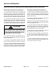


Table Of Contents
- Title Page
- Revision History
- Reader Comments
- Preface
- Table Of Contents
- 1 - Safety
- 2 - Product Records and Maintenance
- 3 - Gasoline Engine
- 4 - Diesel Engine
- 5 - Hydraulic System
- Table of Contents
- Specifications
- General Information
- Operator's Manuals
- Check Hydraulic Fluid Level
- Pushing Traction Unit
- Relieving Hydraulic System Pressure
- Opening Electrical Circuit to Cutting Units
- Traction Circuit Component Failure
- Hydraulic Hoses
- Hydraulic Hose and Tube Installation (O-Ring Face Seal Fitting)
- Hydraulic Fitting Installation (SAE Straight Thread O-Ring Fitting into Component Port)
- Hydraulic Schematic
- Hydraulic Flow Diagrams
- Special Tools
- Troubleshooting
- Testing
- Charge Relief Valve Pressure Test (Using Pressure Gauge)
- Piston (Traction) Pump Flow Test (Using Tester with Flowmeter and Pressure Gauge)
- Wheel Motor Efficiency Test (Using Tester with Flowmeter and Pressure Gauge)
- Steering/Lift Relief Valve Pressure Test (Using Pressure Gauge)
- Lower Cutting Units Relief Valve (RV) Pressure Test (Using Pressure Gauge)
- Steering/Lift Circuit Gear Pump Flow Test (Using Tester with Flowmeter and Pressure Gauge)
- Power Steering Valve Test
- Adjustments
- Service and Repairs
- General Precautions for Removing and Installing Hydraulic System Components
- Flush Hydraulic System
- Filtering Closed-Loop Traction Circuit
- Hydraulic System Start-up
- Gear Pump
- Gear Pump Service
- Piston (Traction) Pump Neutral Assembly
- Piston (Traction) Pump
- Piston (Traction) Pump Service
- Piston Pump Crush Ring Replacement
- Front Wheel Motors
- Rear Wheel Motor (Optional 3WD)
- Wheel Motor Service
- Lift Cylinders
- Lift Cylinder Service
- Lift Control Manifold
- Lift Control Manifold Service
- Control Manifold Cartridge Valve Service
- Power Steering Valve
- Power Steering Valve Service
- Steering Cylinder
- Steering Cylinder Service
- Hydraulic Reservoir
- Leak Detector Tank (Machines Equipped with Optional Turf GuardianTM Leak Detector System)
- Leak Detector Solenoid Valve Assembly (Machines Equipped with Optional Turf GuardianTM Leak Detector System)
- 6 - Electrical System
- Table of Contents
- General Information
- Electrical System Operation
- Turf GuardianTM Leak Detector System Operation (Optional Kit)
- Special Tools
- InfoCenter Display (Serial Number Above 312000000)
- Troubleshooting
- Electrical System Quick Checks
- Adjustments
- Component Testing
- Ignition Switch (Serial Number Below 312000000)
- Ignition Switch (Serial Number Above 312000000)
- Engine Oil Pressure Indicator Light (Greensmaster 3320 with Serial Number Below 312000000)
- Indicator Lights (Greensmaster 3420 with Serial Number Below 312000000)
- Fuse Block (Greensmaster 3320)
- Fuse Block (Greensmaster 3420 with Serial Number Below 312000000)
- Fuse Block (Greensmaster 3420 with Serial Number Above 312000000)
- Electric Reel Drive System (48 Volt DC) Fuses
- Fusible Links
- Hour Meter
- Seat Switch
- Neutral and Mow Switches
- Parking Brake Switch
- Joystick Raise and Lower Switches
- Backlap Switch
- Electric Reel Contactor
- Reel Speed Potentiometer (Serial Number Below 312000000)
- Toro Electronic Controller (TEC)
- Hydraulic Solenoid Valve Coils
- Main Power, Electric Cutting Reels Enable, Charge Circuit (Greensmaster 3320), Glow (Greensmaster 3420) and Fan (Greensmas...
- Kill (Greensmaster 3320) and Start (Greensmaster 3420) Relays
- CAN-bus Termination Resistors
- Electric Reel Circuit Protection Diode
- Location ID Module
- Cutting Reel Motors
- Starter Solenoid (Greensmaster 3320)
- Fuel Pump (Greensmaster 3420)
- Fuel Solenoid (Greensmaster 3420)
- Temperature Sender (Greensmaster 3420)
- Diode Assembly (Greensmaster 3420)
- Turf GuardianTM Leak Detector Oil Level Sensor (If Equipped)
- Turf GuardianTM Leak Detector Alarm (If Equipped)
- Service and Repairs
- Verify Interlock System Operation
- 12 Volt Battery Care
- 12 Volt Battery Storage
- 12 Volt Battery Service
- Electric Reel Drive System (48 Volt DC) Battery Pack Service
- Generator Drive Belt (Greensmaster 3320)
- Generator Drive Belt (Greensmaster 3420)
- Generator Assembly (Greensmaster 3320)
- Generator Assembly (Greensmaster 3420)
- Generator Assembly Service
- Cutting Reel Motor
- Cutting Reel Motor Service
- 7 - Chassis
- 8 - DPA Cutting Units
- 9 - Groomer
- Table of Contents
- Specifications
- General Information
- Troubleshooting
- Adjustments
- Service and Repairs
- Groomer Belt Replacement (Forward Rotating Groomer Drive)
- Groomer Cover (Counter Rotating Groomer Drive)
- Grooming Reel (Forward Rotating Groomer Drive)
- Grooming Reel (Counter Rotating Groomer Drive)
- Grooming Reel Service
- Grooming Reel Bearing Replacement
- Idler Assembly (Forward Rotating Groomer Drive)
- Idler Assembly (Counter Rotating Groomer Drive)
- Lift Arm Assembly
- Groomer Brush
- 10 - Universal Groomer (Optional)
- 11 - Foldout Drawings
- Table of Contents
- Hydraulic Schematic
- Electrical Schematic GR3320
- Electrical Schematic GR3320
- Greensmaster 3320Electrical Schematic(Serial Numbers 314000001 to 316000000)
- Greensmaster 3320Electrical Schematic(Serial Numbers 316000001 to 403410000)
- Greensmaster 3320Electrical Schematic(Serial Numbers above 403410001)
- Electrical Schematic GR3420
- Electrical Schematic GR3420
- Greensmaster 3420Electrical Schematic(Serial Numbers 314003001 to 316000000)
- Greensmaster 3420Electrical Schematic(Serial Numbers 316000001 to 403420000)
- Greensmaster 3420Electrical Schematic(Serial Numbers above 403420001)
- E−Reels Electrical Schematic
- E−Reels Electrical Schematic
- Wire Harness Drawing GR3320
- Wire Harness Diagram GR3320
- Wire Harness Drawing GR3320
- Wire Harness Diagram GR3320
- Wire Harness DrawingGreensmaster 3320(Serial Numbers 316000001 to 403410000)
- Wire Harness DrawingGreensmaster 3320(Serial Numbers 316000001 to 403410000)
- Wire Harness DrawingGreensmaster 3320(Serial Numbers 403410001 to 406000000)
- Wire Harness DiagramGreensmaster 3320(Serial Numbers 403410001 to 406000000)
- Wire Harness DrawingGreensmaster 3320(Serial Numbers above 406000001)
- Wire Harness DiagramGreensmaster 3320(Serial Numbers above 406000001)
- Wire Harness Drawing GR3420
- Wire Harness Diagram GR3420
- Wire Harness Drawing GR3420
- Wire Harness Diagram GR3420
- Wire Harness DrawingGreensmaster 3420(Serial Numbers 314000001 to 316000000)
- Wire Harness DiagramGreensmaster 3420(Serial Numbers 314000001 to 316000000)
- Wire Harness DrawingGreensmaster 3420(Serial Numbers 316000001 to 316000500)
- Wire Harness DiagramGreensmaster 3420(Serial Numbers 316000001 to 316000500)
- Wire Harness DrawingGreensmaster 3420(Serial Numbers 316000501 to 403420000)
- Wire Harness DiagramGreensmaster 3420(Serial Numbers 316000501 to 403420000)
- Wire Harness DrawingGreensmaster 3420(Serial Numbers 403420000 to 405700000)
- Wire Harness DiagramGreensmaster 3420(Serial Numbers 403420000 to 405700000)
- Wire Harness DrawingGreensmaster 3420(Serial Numbers above 405700001)
- Wire Harness DiagramGreensmaster 3420(Serial Numbers above 405700001)
- E−Reels Wire Harness Drawing
- E−Reels Wire Harness Diagram
- E−Reels Wire Harness Drawing
- E−Reels Wire Harness Diagram
- E−Reels Wire Harness Drawing
- E−Reels Wire Harness Diagram

Greensmaster 3320/3420 Hydraulic SystemPage 5 − 49
Hydraulic System Start−up
NOTE: When initially starting the hydraulic system with
new or rebuilt components such as wheel motors,
pumps or lift cylinders, it is important that this start−up
procedure be used. This procedure reduces the chance
of damaging the hydraulic system or its components
from not purging the system of air.
1. After the hydraulic system components have been
properly installed and if the piston pump was rebuilt or
replaced, make sure piston pump housing is at least half
full of clean hydraulic oil.
2. Make sure all hydraulic connections and lines are se-
cured tightly.
3. Make sure hydraulic reservoir is full. Add correct oil
if necessary. Drain, flush and refill hydraulic system res-
ervoir and change oil filter if component failure was se-
vere or system is contaminated.
4. After repairs, check control linkage for proper adjust-
ment, binding or broken parts.
5. Disconnect cutting units from the electrical power
supply by separating the cutting unit power disconnect
couplers on the left side of the operator seat (Fig. 33).
This will prevent unexpected cutting unit operation dur-
ing hydraulic system start−up.
6. Make sure functional control lever is in the neutral
position.
7. Disconnect appropriate electrical component(s) to
prevent the engine from starting:
A. On machines with gasoline engine, disconnect
both spark plug wires from spark plugs.
B. On machines with diesel engine, disconnect wire
harness electrical connector from the engine fuel
stop solenoid.
8. Turn ignition key switch and engage starter for ten
(10) seconds to prime hydraulic pumps. Return ignition
switch to off and wait one (1) minute to allow starter to
cool. Repeat step a second time.
9. Reconnect engine electrical component(s) that were
disabled in step 7 above.
10.Make sure functional control lever is in the neutral
position. Start engine and run at low idle speed. The
charge pump should pick up oil and fill the hydraulic sys-
tem. If there is no indication of fill in thirty (30) seconds,
stop the engine and determine the cause.
11.After the hydraulic system starts to show signs of fill,
accomplish the following:
A. If the gear pump was replaced or rebuilt, run the
engine at low idle speed setting (under no load) for
ten (10) minutes.
B. If the piston pump or a wheel motor was replaced
or rebuilt, move functional control lever to the trans-
port position and run the traction unit so the wheels
turn slowly for ten (10) minutes.
12.Operate the machine (traction, steering and lift cir-
cuits) by gradually increasing the work load to full over
a ten (10) minute period.
13.Stop the machine. Check hydraulic reservoir and fill
if necessary. Check hydraulic components for leaks and
tighten any loose connections.
14.Connect the cutting unit power disconnect couplers
on the left side of the operator seat (Fig. 33).
1. Coupler 2. Stationary coupler
Figure 33
1
2
Hydraulic
System