
Service Manual


TheIdlerAssembly
g251183
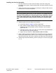
Figure4
1.Socket-headscrew(2each)
9.Stubshaft
2.
10.Flockedseal(2each)
3.Motoradapter11.Bearing
4.Bushing12.Retainingring
5.Idlerarm13.Flangenut
6.O-ring14.Clevispin
7.Locknut(2each)15.Cotterpin
8.Shield16.Collar
Thegroomeridlerassemblyislocatedontheoppositesideofthegroomergear
box.
RemovingtheIdlerAssembly
1.Parkthemachineonacleanandlevelsurface,lowerthecuttingunits
completelytotheground,settheparkingbrake,andremovethekeyfromthe
keyswitch.
2.Removethereelmotorfromthecuttingunit.
3.Removethegroomerreelassembly;refertoRemovingtheGroomerReel
(page10–12).
4.Removethecotterpinandclevispinfromtheheightadjustmentrodatthe
frontoftheidlerarm.Discardthecotterpin.
5.Removethetwosocket-headscrewsthatsecurethemotoradaptertothe
cuttingunit,andremovetheadapterandidlerassembly.Retrieveand
discardtheO-ringandlocknuts.
6.Inspecttheshields,bearing,andbushingintheidlerassembly.Replaceany
componentsthatarewornordamaged.
UniversalGroomer(Optional):ServiceandRepairs
Page10–10
GreensmasterTriFlex™3320/3420
12190SLRevC