
Service Manual


Greensmaster 3320/3420Page 6 − 98Electrical System
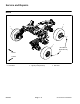
Cutting Reel Motor Service
1. Torx head screw (12 used)
2. Motor cover
3. O−ring
4. Wave washer (2 used)
5. Bearing (2 used)
6. Rotor
7. Bearing (2 used)
8. O−ring (2 used)
9. Housing/controller/cable assembly
10. O−ring
11. Output gear
12. Gearbox cover
13. Shaft seal
14. O−ring
Figure 117
5
7
7
5
6
11
8
1
4
3
10
8
9
12
14
13
2
4
1
35 to 45 in−lb
(4 to 5 N−m)
35 to 45 in−lb
(4 to 5 N−m)
NOTE: If motor housing, controller or cable damage oc-
curs, cutting reel motor replacement is necessary.
These components are not available separately.
Disassembly (Fig. 117)
1. Remove six (6) torx head screws that secure gear-
box cover (item 12) to front of motor housing.
2. Carefully slide gearbox cover from front of motor.
3. Remove and discard O−rings (items 8 and 10) from
gearbox cover.
4. Slide output gear assembly (items 5, 11 and 7) from
motor housing. Remove wave washer (item 4).
5. Remove six (6) torx head screws that secure motor
cover (item 2) to rear of motor housing. Leave cover on
rotor shaft.
IMPORTANT: The rotor magnets are very powerful
and can cause the rotor to shift position very rapidly
during removal. Be cautious during rotor removal to
prevent component damage or personal injury.
6. Use cutting reel motor rotor tool set (see Special
Tools in this chapter) to carefully remove rotor assembly
(items 5, 6 and 7) and motor cover (item 2) from motor
housing.