
Service Manual


Greensmaster 3300/3400Belt Driven Groomer (Optional) Page 9 − 12
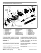
8. Secure driven pulley to grooming reel shaft with lock
nut (item 1). Torque lock nut from 17 to 21 ft−lb (24 to
28 N−m).
NOTE: To prevent cutting reel from turning when instal-
ling drive pulley (item 4), block reel with piece of wood.
9. Secure drive pulley (item 4) to cutting reel shaft.
Torque pulley to 100 ft−lb (135 N−m).
10.Insert front roller into LH groomer arm assembly.
11. Make sure that bushing (item 11) is installed in RH
drive plate assembly.
12.Apply antiseize lubricant to threads of RH groomer
arm lift rod.
13.Position RH groomer arm assembly to front roller,
RH drive plate and cutting unit frame. Secure groomer
arm to cutting unit with plow bolt (item 22), special wash-
er (item 16) and lock nut (item 21).
14.Secure RH groomer arm assembly to drive plate with
spring washer (item 12) and lock nut (item 13).
15.Center front roller to cutting unit and tighten cap
screws (item 10) to secure roller.
16.Install groomer drive belt (item 3) and groomer drive
cover (item 2) to drive plate (see Groomer Belt Replace-
ment in this section).
17.If equipped, install rear roller brush to cutting unit
(see Rear Roller Brush Installation in the Service and
Repairs section of Chapter 8 − DPA Cutting Units).
18.Check grooming reel height and mower height−of−
cut settings. Adjust as needed.
19.Install cutting unit to the machine.
20.Lubricate groomer bearings (see Groomer Installa-
tion Instructions).
NOTE: After greasing groomer bearings, operate
groomer for 30 seconds, stop machine and wipe excess
grease from groomer shaft and seals.