
Service Manual


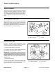
Table Of Contents
- Title Page
- Revision History
- Reader Comments
- Preface
- Table Of Contents
- 1 - Safety
- 2 - Product Records and Maintenance
- 3 - Gasoline Engine
- 4 - Diesel Engine
- 5 - Hydraulic System
- Table of Contents
- Specifications
- General Information
- Operator's Manuals
- Check Hydraulic Fluid Level
- Pushing Traction Unit
- Relieving Hydraulic System Pressure
- Traction Circuit Component Failure
- Hydraulic Hoses
- Hydraulic Hose and Tube Installation (O-Ring Face Seal Fitting)
- Hydraulic Fitting Installation (SAE Straight Thread O-Ring Fitting into Component Port)
- Hydraulic Schematic
- Hydraulic Flow Diagrams
- Special Tools
- Troubleshooting
- Testing
- Charge Relief Valve Pressure Test (Using Tester with Flowmeter and Pressure Gauge)
- Piston (Traction) Pump Flow Test (Using Tester with Flowmeter and Pressure Gauge)
- Wheel Motor Efficiency Test (Using Tester with Flowmeter and Pressure Gauge)
- Steering/Lift Relief Valve Pressure Test (Using Pressure Gauge)
- Lower Cutting Units Relief Valve (RV) Pressure Test (Using Pressure Gauge)
- Steering/Lift Circuit Gear Pump Flow Test (Using Tester with Flowmeter and Pressure Gauge)
- Power Steering Valve Test
- Mow Circuit Gear Pump Flow Test (Using Tester with Flowmeter and Pressure Gauge)
- Mow Circuit Relief Pressure Test (Using Tester with Flowmeter and Pressure Gauge)
- Reel Motor Case Drain Flow Test (Using Tester with Flowmeter and Pressure Gauge)
- Adjustments
- Service and Repairs
- General Precautions for Removing and Installing Hydraulic System Components
- Flush Hydraulic System
- Filtering Closed-Loop Traction Circuit
- Hydraulic System Start-up
- Gear Pump
- Gear Pump Service
- Piston (Traction) Pump Neutral Assembly
- Piston (Traction) Pump
- Piston (Traction) Pump Service
- Piston Pump Crush Ring Replacement
- Front Wheel Motors
- Rear Wheel Motor (Optional 3WD)
- Wheel Motor Service
- Cutting Reel Motors
- Cutting Reel Motor Service
- Mow Control Manifold
- Mow Control Manifold Service
- Control Manifold Cartridge Valve Service
- Lift Cylinders
- Lift Cylinder Service
- Lift Control Manifold
- Lift Control Manifold Service
- Power Steering Valve
- Power Steering Valve Service
- Steering Cylinder
- Steering Cylinder Service
- Hydraulic Reservoir (Machines Equipped with Turf GuardianTM Leak Detector System)
- Hydraulic Reservoir (Machines Not Equipped with Turf GuardianTM Leak Detector System)
- Leak Detector Tank (Machines Equipped with Turf GuardianTM Leak Detector System)
- Leak Detector Solenoid Valve Assembly (Machines Equipped with Turf GuardianTM Leak Detector System)
- 6 - Electrical System
- Table of Contents
- General Information
- Turf GuardianTM Leak Detector System Operation
- Special Tools
- Troubleshooting
- Electrical System Quick Checks
- Adjustments
- Component Testing
- Ignition Switch (Serial Number Below 312000000)
- Ignition Switch (Serial Number Above 312000000)
- Engine Oil Pressure Indicator Light (Greensmaster 3300)
- Indicator Lights (Greensmaster 3400)
- Hour Meter
- Fuse Block (Greensmaster 3300)
- Fuse Block (Greensmaster 3400 with Serial Number Below 312000000)
- Fuse Block (Greensmaster 3400 with Serial Number Above 312000000)
- Fusible Links
- Seat Switch
- Neutral and Mow Switches
- Parking Brake Switch
- Joystick Raise and Lower Switches
- Backlap Switch
- Hydraulic Solenoid Valve Coils
- Main Power, Charge Circuit (Greensmaster 3300), Glow (Greensmaster 3400) and Fan (Greensmaster 3400) Relays
- Kill (Greensmaster 3300) and Start (Greensmaster 3400) Relays
- Toro Electronic Controller (TEC)
- CAN-bus Termination Resistors
- Turf GuardianTM Leak Detector Oil Level Sensor (If Equipped)
- Turf GuardianTM Leak Detector Alarm (If Equipped)
- Starter Solenoid (Greensmaster 3300)
- Fuel Pump (Greensmaster 3400 machines)
- Fuel Solenoid (Greensmaster 3400 machines)
- Temperature Sender (Greensmaster 3400 machines)
- Diode Assembly (Greensmaster 3400)
- Service and Repairs
- 7 - Chassis
- 8 - DPA Cutting Units
- 9 - Belt Driven Groomer (Optional)
- Table of Contents
- Specifications
- General Information
- Troubleshooting
- Adjustments
- Service and Repairs
- Groomer Belt Replacement (Forward Rotating Groomer Drive)
- Groomer Cover (Counter Rotating Groomer Drive)
- Grooming Reel (Forward Rotating Groomer Drive)
- Grooming Reel (Counter Rotating Groomer Drive)
- Grooming Reel Service
- Grooming Reel Bearing Replacement
- Idler Assembly (Forward Rotating Groomer Drive)
- Idler Assembly (Counter Rotating Groomer Drive)
- Lift Arm Assembly
- Groomer Brush
- 10 : Universal Groomer (Optional)
- 11 - Foldout Drawings
- Hydraulic Schematic
- Electrical Schematic Greensmaster 3300(Serial Number Below 312000000)
- Electrical Schematic Greensmaster 3300 (Serial Numbers 312000001 to 314000000)
- Electrical Schematic GR3400
- Greensmaster 3300 Electrical Schematic (Serial Numbers 314000001 to 316000000)
- Greensmaster 3300 Electrical Schematic (Serial Numbers 316000001 to 403410000)
- Greensmaster 3300 Electrical Schematic (Serial Numbers above 403410001)
- Electrical SchematicGreensmaster 3400(Serial Number Below 312000000)
- Electrical Schematic Greensmaster 3400(Serial Number 312000001 to 314000000)
- Greensmaster 3400 Electrical Schematic (Serial Numbers 314000001 to 316000000)
- Greensmaster 3400 Electrical Schematic (Serial Numbers 316000001 to 403420000)
- Greensmaster 3400 Electrical Schematic (Serial Numbers above 403420001)
- Wire Harness Drawing Greensmaster 3300(Serial Number Below 312000000)
- Wire Harness Drawing Greensmaster 3300 (Serial Numbers 312000001 to 316000000)
- Wire Harness Drawing Greensmaster 3300 (Serial Numbers 316000001 to 403410000)
- Wire Harness Drawing Greensmaster 3300 (Serial Numbers 403410001 to 406000000)
- Wire Harness Drawing Greensmaster 3300(Serial Numbers above 406000001)
- Wire Harness Drawing Greensmaster 3400 (Serial Number Below 312000000)
- Wire Harness Drawing Greensmaster 3400 (Serial Numbers 312000000 to 314000000)
- Wire Harness Drawing Greensmaster 3400 (Serial Numbers 314000001 to 316000000)
- Wire Harness Drawing Greensmaster 3400 (Serial Numbers 316000001 to 316000500)
- Wire Harness Drawing Greensmaster 3400 (Serial Numbers 316000501 to 403420000)
- Wire Harness Drawing Greensmaster 3400 (Serial Numbers 403420000 to 405700000)
- Wire Harness Drawing Greensmaster 3400 (Serial Numbers above 405700001)

Greensmaster 3400 Page 4 − 17 Diesel Engine
IMPORTANT: Make sure to not damage the engine,
fuel hoses, hydraulic lines, electrical harness or
other parts while installing the engine. Also, make
sure that hydraulic pump assembly does not shift
location during engine installation.
5. Slowly move the engine assembly toward the hy-
draulic pump assembly to allow the pump coupling to
slide into the engine coupling flange (Fig. 16).
6. Secure hydraulic pump assembly to bell housing on
engine with two (2) cap screws and flat washers (Fig.
16).
7. Secure engine to machine:
A. Secure engine support (item 23) to engine mount
with cap screw, spacer, snubbing washer and flange
nut (Fig. 14).
B. Secure engine rear plate to rear engine mount
with two (2) cap screws, washers and lock nuts (Fig.
15).
8. Connect all electrical harness connectors to engine
using labels placed during engine removal.
9. Connect throttle cable to the swivel on injector pump
speed control lever (Fig. 10). Adjust cable (see Adjust
Throttle Control in the Adjustments section of this chap-
ter).
10.Install exhaust system to machine (see Exhaust Sys-
tem Installation in this section).
11.Install radiator to machine (see Radiator Installation
in this section).
12.Install air cleaner to machine (see Air Cleaner Instal-
lation in this section). Make sure that all hose clamps are
properly tightened.
13.Insert fuel supply hose and fuel return hose through
grommets in engine support on front of engine. Remove
plugs placed during engine removal from hoses. Con-
nect fuel supply hose to the injector pump fitting and fuel
return hose to the #3 injector fitting. Secure fuel hoses
with hose clamps.
14.Open fuel shutoff valve on fuel tank. Check tank and
hoses for leaks.
15.Fill cooling system with coolant. Check radiator and
hoses for leaks.
16.Make sure that alternator belt tension is properly ad-
justed.
17.Bleed fuel system.
18.Make sure that engine oil level is correct.
1. Piston pump
2. Cap screw (2 used)
3. Flat washer (2 used)
4. Coupling
5. Cap screw
6. Spacer
7. Engine coupling flange
8. Bell housing
9. Key
Figure 16
3
1
4
2
7
6
5
8
9
27 to 33 ft−lb
(37 to 44 N−m)
FRONT
Loctite #242
Diesel
Engine