
Service Manual


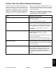


Table Of Contents
- Title Page
- Revision History
- Reader Comments
- Preface
- Table Of Contents
- 1 - Safety
- 2 - Product Records and Maintenance
- 3 - Gasoline Engine
- 4 - Diesel Engine
- 5 - Hydraulic System
- Table of Contents
- Specifications
- General Information
- Operator's Manuals
- Check Hydraulic Fluid Level
- Pushing Traction Unit
- Relieving Hydraulic System Pressure
- Traction Circuit Component Failure
- Hydraulic Hoses
- Hydraulic Hose and Tube Installation (O-Ring Face Seal Fitting)
- Hydraulic Fitting Installation (SAE Straight Thread O-Ring Fitting into Component Port)
- Hydraulic Schematic
- Hydraulic Flow Diagrams
- Special Tools
- Troubleshooting
- Testing
- Charge Relief Valve Pressure Test (Using Tester with Flowmeter and Pressure Gauge)
- Piston (Traction) Pump Flow Test (Using Tester with Flowmeter and Pressure Gauge)
- Wheel Motor Efficiency Test (Using Tester with Flowmeter and Pressure Gauge)
- Steering/Lift Relief Valve Pressure Test (Using Pressure Gauge)
- Lower Cutting Units Relief Valve (RV) Pressure Test (Using Pressure Gauge)
- Steering/Lift Circuit Gear Pump Flow Test (Using Tester with Flowmeter and Pressure Gauge)
- Power Steering Valve Test
- Mow Circuit Gear Pump Flow Test (Using Tester with Flowmeter and Pressure Gauge)
- Mow Circuit Relief Pressure Test (Using Tester with Flowmeter and Pressure Gauge)
- Reel Motor Case Drain Flow Test (Using Tester with Flowmeter and Pressure Gauge)
- Adjustments
- Service and Repairs
- General Precautions for Removing and Installing Hydraulic System Components
- Flush Hydraulic System
- Filtering Closed-Loop Traction Circuit
- Hydraulic System Start-up
- Gear Pump
- Gear Pump Service
- Piston (Traction) Pump Neutral Assembly
- Piston (Traction) Pump
- Piston (Traction) Pump Service
- Piston Pump Crush Ring Replacement
- Front Wheel Motors
- Rear Wheel Motor (Optional 3WD)
- Wheel Motor Service
- Cutting Reel Motors
- Cutting Reel Motor Service
- Mow Control Manifold
- Mow Control Manifold Service
- Control Manifold Cartridge Valve Service
- Lift Cylinders
- Lift Cylinder Service
- Lift Control Manifold
- Lift Control Manifold Service
- Power Steering Valve
- Power Steering Valve Service
- Steering Cylinder
- Steering Cylinder Service
- Hydraulic Reservoir (Machines Equipped with Turf GuardianTM Leak Detector System)
- Hydraulic Reservoir (Machines Not Equipped with Turf GuardianTM Leak Detector System)
- Leak Detector Tank (Machines Equipped with Turf GuardianTM Leak Detector System)
- Leak Detector Solenoid Valve Assembly (Machines Equipped with Turf GuardianTM Leak Detector System)
- 6 - Electrical System
- Table of Contents
- General Information
- Turf GuardianTM Leak Detector System Operation
- Special Tools
- Troubleshooting
- Electrical System Quick Checks
- Adjustments
- Component Testing
- Ignition Switch (Serial Number Below 312000000)
- Ignition Switch (Serial Number Above 312000000)
- Engine Oil Pressure Indicator Light (Greensmaster 3300)
- Indicator Lights (Greensmaster 3400)
- Hour Meter
- Fuse Block (Greensmaster 3300)
- Fuse Block (Greensmaster 3400 with Serial Number Below 312000000)
- Fuse Block (Greensmaster 3400 with Serial Number Above 312000000)
- Fusible Links
- Seat Switch
- Neutral and Mow Switches
- Parking Brake Switch
- Joystick Raise and Lower Switches
- Backlap Switch
- Hydraulic Solenoid Valve Coils
- Main Power, Charge Circuit (Greensmaster 3300), Glow (Greensmaster 3400) and Fan (Greensmaster 3400) Relays
- Kill (Greensmaster 3300) and Start (Greensmaster 3400) Relays
- Toro Electronic Controller (TEC)
- CAN-bus Termination Resistors
- Turf GuardianTM Leak Detector Oil Level Sensor (If Equipped)
- Turf GuardianTM Leak Detector Alarm (If Equipped)
- Starter Solenoid (Greensmaster 3300)
- Fuel Pump (Greensmaster 3400 machines)
- Fuel Solenoid (Greensmaster 3400 machines)
- Temperature Sender (Greensmaster 3400 machines)
- Diode Assembly (Greensmaster 3400)
- Service and Repairs
- 7 - Chassis
- 8 - DPA Cutting Units
- 9 - Belt Driven Groomer (Optional)
- Table of Contents
- Specifications
- General Information
- Troubleshooting
- Adjustments
- Service and Repairs
- Groomer Belt Replacement (Forward Rotating Groomer Drive)
- Groomer Cover (Counter Rotating Groomer Drive)
- Grooming Reel (Forward Rotating Groomer Drive)
- Grooming Reel (Counter Rotating Groomer Drive)
- Grooming Reel Service
- Grooming Reel Bearing Replacement
- Idler Assembly (Forward Rotating Groomer Drive)
- Idler Assembly (Counter Rotating Groomer Drive)
- Lift Arm Assembly
- Groomer Brush
- 10 : Universal Groomer (Optional)
- 11 - Foldout Drawings
- Hydraulic Schematic
- Electrical Schematic Greensmaster 3300(Serial Number Below 312000000)
- Electrical Schematic Greensmaster 3300 (Serial Numbers 312000001 to 314000000)
- Electrical Schematic GR3400
- Greensmaster 3300 Electrical Schematic (Serial Numbers 314000001 to 316000000)
- Greensmaster 3300 Electrical Schematic (Serial Numbers 316000001 to 403410000)
- Greensmaster 3300 Electrical Schematic (Serial Numbers above 403410001)
- Electrical SchematicGreensmaster 3400(Serial Number Below 312000000)
- Electrical Schematic Greensmaster 3400(Serial Number 312000001 to 314000000)
- Greensmaster 3400 Electrical Schematic (Serial Numbers 314000001 to 316000000)
- Greensmaster 3400 Electrical Schematic (Serial Numbers 316000001 to 403420000)
- Greensmaster 3400 Electrical Schematic (Serial Numbers above 403420001)
- Wire Harness Drawing Greensmaster 3300(Serial Number Below 312000000)
- Wire Harness Drawing Greensmaster 3300 (Serial Numbers 312000001 to 316000000)
- Wire Harness Drawing Greensmaster 3300 (Serial Numbers 316000001 to 403410000)
- Wire Harness Drawing Greensmaster 3300 (Serial Numbers 403410001 to 406000000)
- Wire Harness Drawing Greensmaster 3300(Serial Numbers above 406000001)
- Wire Harness Drawing Greensmaster 3400 (Serial Number Below 312000000)
- Wire Harness Drawing Greensmaster 3400 (Serial Numbers 312000000 to 314000000)
- Wire Harness Drawing Greensmaster 3400 (Serial Numbers 314000001 to 316000000)
- Wire Harness Drawing Greensmaster 3400 (Serial Numbers 316000001 to 316000500)
- Wire Harness Drawing Greensmaster 3400 (Serial Numbers 316000501 to 403420000)
- Wire Harness Drawing Greensmaster 3400 (Serial Numbers 403420000 to 405700000)
- Wire Harness Drawing Greensmaster 3400 (Serial Numbers above 405700001)

Greensmaster 3300/3400
DPA Cutting Units
Page 8 − 7
Factors That Can Affect Cutting Performance
There are a number of factors that can contribute to un-
satisfactory quality of cut, some of which may be turf
conditions. Turf conditions such as excessive thatch,
“sponginess” or attempting to cut off too much grass
height may not always be overcome by adjusting the
cutting unit. It is important to remember that the lower
the height−of−cut, the more critical these factors are.
Refer to the Cutting Unit’s Operator’s Manual for de-
tailed cutting unit adjustment procedures. For cutting
unit repair information, refer to the Service and Repairs
section of this chapter.
NOTE: For additional information regarding cutting unit
troubleshooting, see Aftercut Appearance Trouble-
shooting Aid (Toro part no. 00076SL).
Factor
Possible Problem/Correction
Tire pressure Check tire pressure of all traction unit tires. Adjust tire
pressure as necessary.
See the Traction Unit Operator’s manual.
Governed engine speed For best cutting performance and appearance, engine
should be run at maximum governed speed during
machine operation. Check maximum governed engine
speed. Adjust engine to specifications if necessary.
See Chapter 3 − Gasoline Engine or Chapter 4 −
Diesel Engine.
Reel speed All cutting reels must rotate at the same speed (within
100 rpm) (see Troubleshooting in Chapter 5 −
Hydraulic System).
All cutting units must have equal bedknife to reel and
height−of−cut adjustments.
Make sure that reel speed selection is correct (see
Reel Speed Chart in Traction Unit Operator’s Manual).
Reel bearing condition Check reel bearings for wear and replace if necessary.
See Reel Assembly Service in the Service and Repairs
section of this chapter.
Bedknife to reel adjustment Check bedknife to reel contact daily. The bedknife
must have light contact across the entire reel. No
contact will dull the cutting edges. Excessive contact
accelerates wear of both edges. Quality of cut is
adversely affected by both conditions (see Bedknife to
Reel Adjustment in the Cutting Unit Operator’s
Manual).
DPA Cutting
Units