
Service Manual


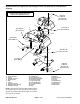

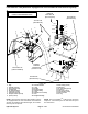


Table Of Contents
- Title Page
- Revision History
- Reader Comments
- Preface
- Table Of Contents
- 1 - Safety
- 2 - Product Records and Maintenance
- 3 - Gasoline Engine
- 4 - Diesel Engine
- 5 - Hydraulic System
- Table of Contents
- Specifications
- General Information
- Operator's Manuals
- Check Hydraulic Fluid Level
- Pushing Traction Unit
- Relieving Hydraulic System Pressure
- Traction Circuit Component Failure
- Hydraulic Hoses
- Hydraulic Hose and Tube Installation (O-Ring Face Seal Fitting)
- Hydraulic Fitting Installation (SAE Straight Thread O-Ring Fitting into Component Port)
- Hydraulic Schematic
- Hydraulic Flow Diagrams
- Special Tools
- Troubleshooting
- Testing
- Charge Relief Valve Pressure Test (Using Tester with Flowmeter and Pressure Gauge)
- Piston (Traction) Pump Flow Test (Using Tester with Flowmeter and Pressure Gauge)
- Wheel Motor Efficiency Test (Using Tester with Flowmeter and Pressure Gauge)
- Steering/Lift Relief Valve Pressure Test (Using Pressure Gauge)
- Lower Cutting Units Relief Valve (RV) Pressure Test (Using Pressure Gauge)
- Steering/Lift Circuit Gear Pump Flow Test (Using Tester with Flowmeter and Pressure Gauge)
- Power Steering Valve Test
- Mow Circuit Gear Pump Flow Test (Using Tester with Flowmeter and Pressure Gauge)
- Mow Circuit Relief Pressure Test (Using Tester with Flowmeter and Pressure Gauge)
- Reel Motor Case Drain Flow Test (Using Tester with Flowmeter and Pressure Gauge)
- Adjustments
- Service and Repairs
- General Precautions for Removing and Installing Hydraulic System Components
- Flush Hydraulic System
- Filtering Closed-Loop Traction Circuit
- Hydraulic System Start-up
- Gear Pump
- Gear Pump Service
- Piston (Traction) Pump Neutral Assembly
- Piston (Traction) Pump
- Piston (Traction) Pump Service
- Piston Pump Crush Ring Replacement
- Front Wheel Motors
- Rear Wheel Motor (Optional 3WD)
- Wheel Motor Service
- Cutting Reel Motors
- Cutting Reel Motor Service
- Mow Control Manifold
- Mow Control Manifold Service
- Control Manifold Cartridge Valve Service
- Lift Cylinders
- Lift Cylinder Service
- Lift Control Manifold
- Lift Control Manifold Service
- Power Steering Valve
- Power Steering Valve Service
- Steering Cylinder
- Steering Cylinder Service
- Hydraulic Reservoir (Machines Equipped with Turf GuardianTM Leak Detector System)
- Hydraulic Reservoir (Machines Not Equipped with Turf GuardianTM Leak Detector System)
- Leak Detector Tank (Machines Equipped with Turf GuardianTM Leak Detector System)
- Leak Detector Solenoid Valve Assembly (Machines Equipped with Turf GuardianTM Leak Detector System)
- 6 - Electrical System
- Table of Contents
- General Information
- Turf GuardianTM Leak Detector System Operation
- Special Tools
- Troubleshooting
- Electrical System Quick Checks
- Adjustments
- Component Testing
- Ignition Switch (Serial Number Below 312000000)
- Ignition Switch (Serial Number Above 312000000)
- Engine Oil Pressure Indicator Light (Greensmaster 3300)
- Indicator Lights (Greensmaster 3400)
- Hour Meter
- Fuse Block (Greensmaster 3300)
- Fuse Block (Greensmaster 3400 with Serial Number Below 312000000)
- Fuse Block (Greensmaster 3400 with Serial Number Above 312000000)
- Fusible Links
- Seat Switch
- Neutral and Mow Switches
- Parking Brake Switch
- Joystick Raise and Lower Switches
- Backlap Switch
- Hydraulic Solenoid Valve Coils
- Main Power, Charge Circuit (Greensmaster 3300), Glow (Greensmaster 3400) and Fan (Greensmaster 3400) Relays
- Kill (Greensmaster 3300) and Start (Greensmaster 3400) Relays
- Toro Electronic Controller (TEC)
- CAN-bus Termination Resistors
- Turf GuardianTM Leak Detector Oil Level Sensor (If Equipped)
- Turf GuardianTM Leak Detector Alarm (If Equipped)
- Starter Solenoid (Greensmaster 3300)
- Fuel Pump (Greensmaster 3400 machines)
- Fuel Solenoid (Greensmaster 3400 machines)
- Temperature Sender (Greensmaster 3400 machines)
- Diode Assembly (Greensmaster 3400)
- Service and Repairs
- 7 - Chassis
- 8 - DPA Cutting Units
- 9 - Belt Driven Groomer (Optional)
- Table of Contents
- Specifications
- General Information
- Troubleshooting
- Adjustments
- Service and Repairs
- Groomer Belt Replacement (Forward Rotating Groomer Drive)
- Groomer Cover (Counter Rotating Groomer Drive)
- Grooming Reel (Forward Rotating Groomer Drive)
- Grooming Reel (Counter Rotating Groomer Drive)
- Grooming Reel Service
- Grooming Reel Bearing Replacement
- Idler Assembly (Forward Rotating Groomer Drive)
- Idler Assembly (Counter Rotating Groomer Drive)
- Lift Arm Assembly
- Groomer Brush
- 10 : Universal Groomer (Optional)
- 11 - Foldout Drawings
- Hydraulic Schematic
- Electrical Schematic Greensmaster 3300(Serial Number Below 312000000)
- Electrical Schematic Greensmaster 3300 (Serial Numbers 312000001 to 314000000)
- Electrical Schematic GR3400
- Greensmaster 3300 Electrical Schematic (Serial Numbers 314000001 to 316000000)
- Greensmaster 3300 Electrical Schematic (Serial Numbers 316000001 to 403410000)
- Greensmaster 3300 Electrical Schematic (Serial Numbers above 403410001)
- Electrical SchematicGreensmaster 3400(Serial Number Below 312000000)
- Electrical Schematic Greensmaster 3400(Serial Number 312000001 to 314000000)
- Greensmaster 3400 Electrical Schematic (Serial Numbers 314000001 to 316000000)
- Greensmaster 3400 Electrical Schematic (Serial Numbers 316000001 to 403420000)
- Greensmaster 3400 Electrical Schematic (Serial Numbers above 403420001)
- Wire Harness Drawing Greensmaster 3300(Serial Number Below 312000000)
- Wire Harness Drawing Greensmaster 3300 (Serial Numbers 312000001 to 316000000)
- Wire Harness Drawing Greensmaster 3300 (Serial Numbers 316000001 to 403410000)
- Wire Harness Drawing Greensmaster 3300 (Serial Numbers 403410001 to 406000000)
- Wire Harness Drawing Greensmaster 3300(Serial Numbers above 406000001)
- Wire Harness Drawing Greensmaster 3400 (Serial Number Below 312000000)
- Wire Harness Drawing Greensmaster 3400 (Serial Numbers 312000000 to 314000000)
- Wire Harness Drawing Greensmaster 3400 (Serial Numbers 314000001 to 316000000)
- Wire Harness Drawing Greensmaster 3400 (Serial Numbers 316000001 to 316000500)
- Wire Harness Drawing Greensmaster 3400 (Serial Numbers 316000501 to 403420000)
- Wire Harness Drawing Greensmaster 3400 (Serial Numbers 403420000 to 405700000)
- Wire Harness Drawing Greensmaster 3400 (Serial Numbers above 405700001)

Greensmaster 3300/3400 Hydraulic SystemPage 5 − 109
Removing Hydraulic Reservoir (Fig. 78)
1. Park machine on a level surface, set brake, lower
cutting units and stop engine. Remove key from the igni-
tion switch.
CAUTION
Before continuing further, read and become fa-
miliar with General Precautions for Removing
and Installing Hydraulic System Components in
this section.
2. Disconnect oil level sensor wire connector from ma-
chine wire harness.
3. Remove leak detector tank (see Leak Detector Tank
Removal in this section).
4. Remove leak detector solenoid valve assembly from
hydraulic reservoir (see Leak Detector Solenoid Valve
Assembly in this section).
5. Completely drain hydraulic oil from hydraulic reser-
voir through gear pump inlet (suction) hose into a suit-
able container.
6. Label hydraulic reservoir hoses for assembly pur-
poses. Thoroughly clean hydraulic hose ends prior to
disconnecting the hoses from reservoir fittings.
7. Remove hose assemblies and O−rings from reser-
voir fittings. Allow hoses to drain into suitable container.
8. Put clean caps or plugs on disconnected hoses and
fittings to prevent contamination.
9. To allow easier access to fasteners that secure hy-
draulic reservoir, raise and support tank mount plate as-
sembly (hydraulic reservoir, fuel tank and tank mount
plate) (see Tank Mount Plate Assembly in the Service
and Repairs section of Chapter 7 − Chassis).
10.Remove four (4) cap screws (item 17), flat washers
(item 16) and flange bushings (item 15) that secure the
hydraulic reservoir (item 2) to the tank mount plate.
11.Remove hydraulic reservoir from machine.
12.If hydraulic fittings are to be removed from reservoir,
mark fitting orientation to allow correct assembly. Re-
move hydraulic fittings from hydraulic reservoir as need-
ed. Discard O−rings from removed fittings.
13.Remove oil level sensor (item 11) from hydraulic res-
ervoir. Discard O−ring from sensor.
14.Clean hydraulic reservoir and reservoir components
with clean solvent. Inspect reservoir for leaks, cracks or
other damage.
Installing Hydraulic Reservoir (Fig. 78)
1. Lubricate and place new O−rings onto all removed
fittings. Install fittings into reservoir openings. Use
marks made during the removal process to correctly
orientate fittings. Refer to Figure 78 for reservoir fitting
installation torque specifications.
2. Install oil level sensor into reservoir making sure that
arrow on sensor is pointing down (Fig. 79). Torque sen-
sor nut from 110 to 140 in−lb (12.5 to 15.8 N−m).
3. Position hydraulic reservoir onto tank mount plate.
4. Apply antiseize lubricant to threads of four (4) cap
screws (item 17). Secure hydraulic reservoir to the tank
mount plate with four (4) cap screws, flat washers (item
16) and flange bushings (item 15). Torque cap screws
from 30 to 50 in−lb (3.4 to 5.6 N−m).
5. Lower and secure tank mount plate assembly (hy-
draulic reservoir, fuel tank and tank mount plate) (see
Tank Mount Plate Assembly in the Service and Repairs
section of Chapter 7 − Chassis).
6. Remove caps and plugs from disconnected hydrau-
lic hoses and reservoir fittings.
7. Lubricate and position new O−rings to fittings on res-
ervoir. Use labels placed during the removal process to
properly install hydraulic lines to reservoir fittings (see
Hydraulic Hose and Tube Installation in the General In-
formation section of this chapter).
8. Install leak detector solenoid valve assembly to hy-
draulic reservoir (see Leak Detector Solenoid Valve As-
sembly in this section).
9. Install leak detector tank (see Leak Detector Tank
Installation in this section).
10.Connect oil level sensor wire connector to machine
wire harness.
11.Fill hydraulic reservoir with new hydraulic oil.
12.Verify leak detector operation.
1. Oil level sensor 2. Sensor arrow
Figure 79
1
2
Hydraulic
System