
Service Manual


Greensmaster 3250−DHydraulic System Page 4 − 102
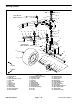
Hydraulic Reservoir
1. Strainer
2. 90
o
hydraulic fitting
3. Fuel tank clamp
4. Washer head screw (2 used)
5. Tank cap
6. Hydraulic tank
7. Hydraulic straight fitting
8. Oil filter assembly
9. Hydraulic barb fitting
10. Oil filter mount
11. O−ring
12. Flat washer (4 used)
13. Grommet (4 used)
14. O−ring
15. Hose clamp
16. Cap screw (4 used)
17. Filter screen
18. Cap screw (3 used)
19. Plug
20. Air breather
21. Return hose
22. Tube assembly
23. Hose clamp
24. Serrated plug
25. O−ring
26. O−ring
27. O−ring
28. O−ring
29. Mounting plate
30. Hydraulic hose
31. Hydraulic hose
32. Breather adapter
Figure 70
v
3
6
10
16
12
13
9
15
18
20
2
1
16
4
22
7
23
19
23
8
24
5
18
17
9
21
11
25
14
28
27
26
29
30 to 60 in−lb
(3.4 to 6.8 N−m)
30
31
32
Antiseize
Lubricant
Removing Hydraulic Reservoir (Fig. 70)
1. Park the machine on a level surface, engage the
parking brake, lower the cutting units and stop the en-
gine. Remove key from the ignition switch.
CAUTION
Before continuing further, read and become fa-
miliar with General Precautions for Removing
and Installing Hydraulic System Components.
2. Place a suitable container under the gear pump to
collect hydraulic oil. Clamp pump inlet hose to prevent
drainage (Fig. 71). Remove pump inlet hose from gear
pump and direct to container. Release clamp from hose
to drain hydraulic tank.
3. Disconnect hose assembly from the hydraulic fitting
welded to the reel motor case drain tube located below
the right side of the frame. Allow hose to drain to a suit-
able container (Fig. 72).
4. Disconnect return hose (item 21) from barb fitting
(item 9). Allow hose to drain into a suitable container.