
Operator's Manual


g019975
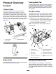
Figure4
1.Rollbar
3.Locknut(5/8inch)
2.Bolt(5/8x4-1/2inch)
2.Lowertherollbarontotheframe,aligningitwith
themountingholes(Figure4).
3.Secureeachsideoftherollbartotheframe
with2bolts(5/8x4-1/2inches)andlocknutsas
showninFigure4.
4.Torquethefastenersto183to223N∙m(135to
165ft-lb).
4
ReducingtheTirePressure
NoPartsRequired
Procedure
Thetiresareover-inatedatthefactoryforshipping
purposes.Reducethepressuretotheproperlevels
beforestartingthemachine.RefertoCheckingthe
TirePressure(page39).
5
MountingtheFrontCarrier
Frames
Partsneededforthisprocedure:
2
Carrierframe
2
Spacer
2
Bolt(1/2inchx3-1/4inches)
2
Locknut(1/2inch)
Procedure
1.Mountacarrierframeassemblytoeachclevis
withaspacer,bolt(1/2x3-1/4inch),andlocknut
(1/2inch);refertoFigure5.Torqueto91to113
N∙m(67to83ft/lb).
g016465
Figure5
1.Carrierframe4.Bolt(1/2x3-1/4inches)
2.Spacer5.Locknut(1/2inch)
3.Clevis
2.Lubricatethebushingsineachcarrierframewith
No.2lithiumgrease.
11