
Service Manual


Reel Service (Fig. 16)
Note: Install new reel components on each end of the
reel shaft that mates with newly serviced side plate com-
ponents.
1. Remove the retaining ring (5) and the drive coupler
(4) from the end of the reel shaft.
2. Remove the V–ring (3) from the reel shaft.
3. Using a flat blade screw driver or similar tool, re-
move the speedi sleeve (2) from the reel shaft.
12
3
Figure 19
Note: Replacemant Seal Kit (Toro Part No. 106-6937)
1. Reel shaft 3. Adapter spline
is available for reel service of dual point adjust cutting
2. Drive adapter
units.
4. Inspect the reel shaft as follows:
3
5
2
A. Check the reel shaft for bending and distortion
by placing the shaft ends in V–blocks. Replace the
reel if necessary.
B. Check the reel blades for bending or cracking
Replace the reel if necessary
.
C. Check the drive adapter inside of the reel shaft
(Fig. 19). The adapter should be free of bending and
distortion. Check the splines for excessive cracks or
distortion. Replace the reel if necessary.
D. Check the service limit of the reel diameter. Re -
place the reel if necessary.
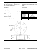
5. Using an appropriate I.D. tube or sleeve, press the
speedi sleeve onto the reel shaft until it bottoms out on
the spider cup (Fig. 20).
4
1
.104 Seal Depth
IMPORTANT: Do not nick or scratch the Speedi
sleeve surface as seal failure could result.
Figure 20
6. Slide the V–ring onto the reel shaft with the thick
1. Outer seal 4. V-ring
shoulder of the V–ring facing inward (Fig. 20).
2. Inner seal 5. Left side plate
3. Speedi sleeve
7. Fill the drive coupling (4) 1/2 to 1/3 full with Mobil
High Temperature HP or equivalent grease. Also, coat
the outside of the drive coupling with grease.
8. Install the retaining ring (5). Make sure it is seated
into the groove.
Greensmaster 3100 Page 10 - 17
Re
v. D Dual Point Adjust Cutting units