
Operator's Manual


Note:Ensurethatthenutsorbackofthe
bedbaradjustingscrewsarenotrestingonthe
worksurface(Figure3).
3.Rotatethereelsothat1ofthebladescrosses
thebedknifeedgebetweentherstandsecond
bedknifescrewheadslocatedontherightside
ofthecuttingunit.
4.Makeandidentifyingmarkonthebladewhereit
crossesthebedknifeedge.
Note:Thiswillmakelateradjustmentseasier.
5.Inserta0.05mm(0.002inch)shimbetweenthe
bladeandthebedknifeedgeatthepointmarked
instep4.
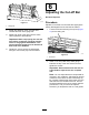
6.Turntherightbedbaradjustingscrew(Figure4)
untilyoufeellightpressureontheshimwhen
slidingitside-to-side.Removetheshim.
g014595
Figure4
1.Bedbar-adjustingscrew
7.Fortheleftsideofthecuttingunit,slowlyrotate
thereelsothattheclosestbladecrossesthe
bedknifeedgebetweentherstandsecond
screwheads.
8.Repeatsteps4through6fortheleftsideofthe
cuttingunitandleftbedbaradjustingscrew.
9.Repeatsteps5and6untilthereislightpressure
atthecontactpointsonboththeleftandright
sidesofthecuttingunit.
10.Toobtainlightcontactbetweenthereeland
bedknife,turneachbedbaradjustingscrew
clockwise3click.
Note:Eachclickonthebedbaradjustingscrew
movesthebedknife0.018mm(0.0007inch).Do
notovertightentheadjustingscrews.
Turningtheadjustingscrewclockwisemoves
thebedknifeedgeclosertothereel.Turningthe
adjustingscrewcounterclockwisemovesthe
bedknifeedgeawayfromthereel.
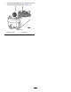
11.Testthecuttingperformancebyinsertingalong
stripofcuttingperformancepaperbetweenthe
reelandbedknife,perpendiculartothereel
andbedknife(Figure5).Slowlyrotatethereel
forwardtocutthepaper.
g014411
Figure5
5