
Service Manual


Greensmaster 1000Grooming Reel Kit Page 8 − 20
Cutting Reel
Removal
1. Park mower on a level surface. Make sure engine
is OFF. Remove high tension lead from the spark plug.
2. Make sure mower is on a flat level surface or on a
stable work bench.
3. Remove grooming reel kit following the Removal
instructions in Frame Assemblies (RH and LH).
4. Remove bedbar from the mower (see Bedbar Re-
moval in Service and Repairs section of Chapter 7 − Cut-
ting Unit).
5. Remove grease fittings from both bearing housings.
Mark bearing housing (RH) for reassembly purposes
(Fig. 32 and 33).
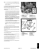
6. Remove the the bearing lock nut from the reel drive
shaft as follows (Fig. 33):
A. Tip up the unit to access the bottom of the reel.
B. Insert a long−handled pry bar (3/8 x 12 inch with
screwdriver handle recommended) through the bot-
tom of the cutting unit. The pry bar should pass be-
tween the top of the reel shaft and the backs of the
reel blades so that the reel will not move.
IMPORTANT: To avoid grinding the reel, do not
contact the cutting edge of any blade with the
pry bar as this may damage the cutting edge
and/or cause a high blade.
C. Move the pry bar against the weld side of the reel
support plate closest to the bearing lock nut
.
D. Rest the handle of the pry bar against the front
roller and remove the bearing lock nut.
E. Tip the unit back onto its rollers.
7. Pull both bearing housings from the frame and reel
(Fig. 32 and 33). Remove the reel from the mower.
8. If bearings are worn or need replacement for main-
tenance purposes, remove bearings from both bearing
housings as follows:
A. Remove bearing seal, retaining ring, bearing,
and wave washer from the bearing housing (RH).
Discard wave washer (Fig. 32).
B. Remove large seal, small seal, and bearing from
the bearing housing (LH) (Fig. 33).
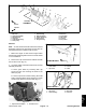
1. Grease fitting
2. Bearing housing (RH)
3. Frame
4. Large seal
5. Small seal
6. Retaining ring
7. Bearing
8. Wave washer
Figure 32
FRONT
1
2
7
6
4
8
5
3
RIGHT
1. Grease fitting
2. Bearing housing (LH)
3. Bearing lock nut
4. Large seal
5. Small seal
6. Bearing
7. Frame
Figure 33
LEFT
FRONT
7
5
1
2
4
6
3
Installation
1. Make sure engine is OFF. Remove high tension
lead from the spark plug. Place mower on a flat level sur-
face or on a stable work bench.
IMPORTANT: Make sure correct bearing housing is
used when installing bearings. The grease fitting
hole should face forward when the housing is
placed in the frame.
2. Reassemble bearing housing (RH) components
(Fig. 32).