
Service Manual


Table Of Contents
- Title Page
- Revision History
- Reader Comments
- Preface
- Table Of Contents
- 1 : Safety
- 2 : Product Records and Maintenance
- 3 : Engine
- SUBARU SERVICE MANUAL
- 4 : Traction and Reel Drive System
- Table of Contents
- Specifications
- General Information
- Special Tools
- Adjustments
- Service and Repairs
- Reel Drive Belt
- Reel Drive Assembly
- Reel Drive Bearing Housing
- Drum Drive Belt
- Drum Drive Idler Assembly
- Traction Drums
- Differential Assembly
- Differential Assembly Service
- Transmission Drive Belt
- Transmission Idler System
- Transmission Reel Drive System
- Removing Seized Reel Clutch Shaft From Transmission
- Transmission Clutch System (1800/2100)
- Clutch Assembly Service (1800/2100)
- Transmission Clutch System (1820/2120)
- Clutch Assembly Service (1820/2120)
- Clutch Shaft Service (1820/2120)
- Transmission Drum Drive System
- Transmission
- 5 : Electrical System
- 6 : Chassis and Controls
- 7 : Cutting Unit
- 8 : Belt Driven Groomer (Optional)
- Table of Contents
- Specifications
- General Information
- Troubleshooting
- Adjustments
- Service and Repairs
- Groomer Belt Replacement (Forward Rotating Groomer Drive)
- Groomer Cover (Counter Rotating Groomer Drive)
- Grooming Reel (Forward Rotating Groomer Drive)
- Grooming Reel (Counter Rotating Groomer Drive)
- Grooming Reel Service
- Grooming Reel Bearing Replacement
- Idler Assembly (Forward Rotating Groomer Drive)
- Idler Assembly (Counter Rotating Groomer Drive)
- Lift Arm Assembly
- Groomer Brush
- 9: Universal Groomer (Optional)
Greensmaster Flex 1800/1820/2100/2120Traction and Reel Drive System Page 4 − 48
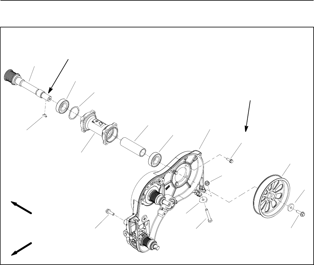
Transmission Drum Drive System
Figure 55
1. Transmission housing
2. Extension housing
3. Ball bearing (2 used)
4. Driven pulley (traction drum drive)
5. Hardened washer (2 used)
6. Driven pulley
7. Spacer
8. Wave washer
9. Woodruff key
10. Washer head screw (4 used)
11. Flange nut
12. Flange head screw (2 used)
13. Cap screw
FRONT
RIGHT
6
5
5
2
4
3
3
1
7
8
9
10
11
1212
13
See text for
tightening
procedure
Lubricant
Antiseize
Transmission removal from the machine is not neces-
sary to service the transmission drum drive system
shown in Figure 55. Transmission drum drive compo-
nents can be accessed by removing the engine from the
frame, removing the transmission cover and then re-
moving the drive belt.
Disassembly (Fig. 55)
1. Park machine on a level surface. Make sure engine
is OFF.
2. Remove transmission drive belt (see Transmission
Drive Belt in this section).
3. Remove flange head screw (item 12) and hardened
washer (item 5) that secure driven pulley (item 6) to
shaft. Slide pulley from shaft. Locate and retrieve wood-
ruff key (item 9).
4. Remove drum drive belt from machine (see Drum
Drive Belt in this section).
5. Slide traction drum drive driven pulley (item 4) from
extension housing.
6. If necessary, remove ball bearings (item 3), spacer
(item 7) and wave washer (item 8) from extension hous-
ing.