
Service Manual

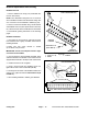


Table Of Contents
- Title Page
- Revision History
- Reader Comments
- Preface
- Table Of Contents
- 1 : Safety
- 2 : Product Records and Maintenance
- 3 : Engine
- SUBARU SERVICE MANUAL
- 4 : Traction and Reel Drive System
- Table of Contents
- Specifications
- General Information
- Special Tools
- Adjustments
- Service and Repairs
- Reel Drive Belt
- Reel Drive Assembly
- Reel Drive Bearing Housing
- Drum Drive Belt
- Drum Drive Idler Assembly
- Traction Drums
- Differential Assembly
- Differential Assembly Service
- Transmission Drive Belt
- Transmission Idler System
- Transmission Reel Drive System
- Removing Seized Reel Clutch Shaft From Transmission
- Transmission Clutch System (1800/2100)
- Clutch Assembly Service (1800/2100)
- Transmission Clutch System (1820/2120)
- Clutch Assembly Service (1820/2120)
- Clutch Shaft Service (1820/2120)
- Transmission Drum Drive System
- Transmission
- 5 : Electrical System
- 6 : Chassis and Controls
- 7 : Cutting Unit
- 8 : Belt Driven Groomer (Optional)
- Table of Contents
- Specifications
- General Information
- Troubleshooting
- Adjustments
- Service and Repairs
- Groomer Belt Replacement (Forward Rotating Groomer Drive)
- Groomer Cover (Counter Rotating Groomer Drive)
- Grooming Reel (Forward Rotating Groomer Drive)
- Grooming Reel (Counter Rotating Groomer Drive)
- Grooming Reel Service
- Grooming Reel Bearing Replacement
- Idler Assembly (Forward Rotating Groomer Drive)
- Idler Assembly (Counter Rotating Groomer Drive)
- Lift Arm Assembly
- Groomer Brush
- 9: Universal Groomer (Optional)

Greensmaster Flex 1800/1820/2100/2120 Page 7 − 17 Cutting Unit
3. Slide bedbar adjuster shaft (item 4) into flange bush-
ings in cutting unit side plate. Secure adjuster shaft with
wave washer (item 8) and retaining ring (item 9).
NOTE: Bedbar adjuster shaft (item 4) has left−hand
threads.
4. Apply antiseize lubricant to threads of bedbar adjust-
er screw that fit into adjuster shaft. Thread bedbar ad-
juster screw (item 10) into adjuster shaft.
5. Install bedbar (see Bedbar Installation in this sec-
tion).
6. Install washer (item 11), spring (item 2) and lock nut
(item 3) onto adjuster screw. Tighten the lock nut on
each bedbar adjuster assembly until the compression
spring is fully compressed, then loosen lock nut 1/2 turn.
7. Adjust cutting unit (see Cutting Unit Operator’s
Manual).
1. Crossmember
2. Detent
3. Cap screw
Figure 26
1
23
Flex 1800/1820 Shown
Cutting Unit