
Service Manual


Table Of Contents
- Title Page
- Revision History
- Reader Comments
- Preface
- Table Of Contents
- 1 : Safety
- 2 : Product Records and Maintenance
- 3 : Engine
- SUBARU SERVICE MANUAL
- 4 : Traction and Reel Drive System
- Table of Contents
- Specifications
- General Information
- Special Tools
- Adjustments
- Service and Repairs
- Reel Drive Belt
- Reel Drive Assembly
- Reel Drive Bearing Housing
- Drum Drive Belt
- Drum Drive Idler Assembly
- Traction Drums
- Differential Assembly
- Differential Assembly Service
- Transmission Drive Belt
- Transmission Idler System
- Transmission Reel Drive System
- Removing Seized Reel Clutch Shaft From Transmission
- Transmission Clutch System (1800/2100)
- Clutch Assembly Service (1800/2100)
- Transmission Clutch System (1820/2120)
- Clutch Assembly Service (1820/2120)
- Clutch Shaft Service (1820/2120)
- Transmission Drum Drive System
- Transmission
- 5 : Electrical System
- 6 : Chassis and Controls
- 7 : Cutting Unit
- 8 : Belt Driven Groomer (Optional)
- Table of Contents
- Specifications
- General Information
- Troubleshooting
- Adjustments
- Service and Repairs
- Groomer Belt Replacement (Forward Rotating Groomer Drive)
- Groomer Cover (Counter Rotating Groomer Drive)
- Grooming Reel (Forward Rotating Groomer Drive)
- Grooming Reel (Counter Rotating Groomer Drive)
- Grooming Reel Service
- Grooming Reel Bearing Replacement
- Idler Assembly (Forward Rotating Groomer Drive)
- Idler Assembly (Counter Rotating Groomer Drive)
- Lift Arm Assembly
- Groomer Brush
- 9: Universal Groomer (Optional)
Greensmaster Flex 1800/1820/2100/2120Page 6 − 14Chassis and Controls
4. Connect spring (item 11 in Figure 15) between trac-
tion lever assembly and operator presence control.
5. Connect wire harness connector to traction switch
(Fig. 15).
6. Connect reel clutch and traction clutch cables to le-
ver assembly (see Cable Replacement in this section).
Check cable operation and adjust as necessary.
7. Check adjustment of traction switch (see Traction
Switch in the Adjustments section of Chapter 5 − Electri-
cal System). Adjust switch if necessary.
8. Install console cover to handle.
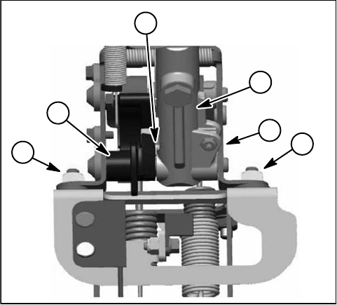
1. Transport lever
2. Reel shaft lever
3. Clearance location
4. Shifter bracket
5. Screw and nut
Figure 17
1
2
3
5
5
4