
Service Manual


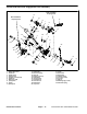
Table Of Contents
- Title Page
- Revision History
- Reader Comments
- Preface
- Table Of Contents
- 1 : Safety
- 2 : Product Records and Maintenance
- 3 : Engine
- SUBARU SERVICE MANUAL
- 4 : Traction and Reel Drive System
- Table of Contents
- Specifications
- General Information
- Special Tools
- Adjustments
- Service and Repairs
- Reel Drive Belt
- Reel Drive Assembly
- Reel Drive Bearing Housing
- Drum Drive Belt
- Drum Drive Idler Assembly
- Traction Drums
- Differential Assembly
- Differential Assembly Service
- Transmission Drive Belt
- Transmission Idler System
- Transmission Reel Drive System
- Removing Seized Reel Clutch Shaft From Transmission
- Transmission Clutch System (1800/2100)
- Clutch Assembly Service (1800/2100)
- Transmission Clutch System (1820/2120)
- Clutch Assembly Service (1820/2120)
- Clutch Shaft Service (1820/2120)
- Transmission Drum Drive System
- Transmission
- 5 : Electrical System
- 6 : Chassis and Controls
- 7 : Cutting Unit
- 8 : Belt Driven Groomer (Optional)
- Table of Contents
- Specifications
- General Information
- Troubleshooting
- Adjustments
- Service and Repairs
- Groomer Belt Replacement (Forward Rotating Groomer Drive)
- Groomer Cover (Counter Rotating Groomer Drive)
- Grooming Reel (Forward Rotating Groomer Drive)
- Grooming Reel (Counter Rotating Groomer Drive)
- Grooming Reel Service
- Grooming Reel Bearing Replacement
- Idler Assembly (Forward Rotating Groomer Drive)
- Idler Assembly (Counter Rotating Groomer Drive)
- Lift Arm Assembly
- Groomer Brush
- 9: Universal Groomer (Optional)

Greensmaster Flex 1800/1820/2100/2120 Page 6 − 9 Chassis and Controls
Installation
1. Secure traction clutch cable to the traction lever as-
sembly (Fig. 10):
A. Install cable spring to spring anchor on lever as-
sembly.
B. Slide the cable housing into the shift mount
bracket slot. Make sure that a jam nut, flat washer
and lock washer are on both sides of bracket. Adjust
jam nuts so that equal amount of cable threads are
visible above and below jam nuts. Leave jam nuts
snug until final cable adjustment.
2. Route traction clutch cable to the transmission and
install cable to transmission (Fig. 9):
A. Secure cable eyelet to transmission traction lever
with flange nut.
B. Position traction cable to the casting slot of trans-
mission with a jam nut, flat washer and lock washer
on each side of the slot. Adjust and tighten jam nuts
so that equal amount of cable threads are visible
above and below jam nuts.
3. Make final traction clutch cable adjustment at trac-
tion lever assembly. Adjust cable jam nuts to remove
slack in cable without rotating the transmission bell-
crank lever more than 3
o
(approximately 0.060” (1.5
mm) at slot).
4. Install console cover to handle assembly.
1. Traction clutch cable
2. Transmission
3. Traction cable bracket
4. Flange nut
5. Bellcrank lever
Figure 9
1
2
3
4
5
1. Shift handle
2. Traction clutch cable
3. Reel clutch cable
4. Traction cable spring
5. Upper cable jam nut
6. Lower cable jam nut
7. Shift mount bracket
Figure 10
1
2
3
4
5
7
6
Chassis and
Controls