
Service Manual


Greensmaster 1000 Grooming Reel KitPage 8 − 17
Note: The driven pulley (42) has left handed threads.
B. Use an allen wrench to remove driven pulley
from the shaft (53).
11. Remove lock nut and flat washer from the shaft of
the clutch drive adapter. Pull clutch assembly off the
shaft of the clutch drive adapter (Fig. 18).
12. Remove the clutch adapter from reel shaft as fol-
lows (Fig. 24):
A. Tip up the unit to access the bottom of the reel.
B. Insert a long−handled pry bar (3/8 x 12 inch with
screwdriver handle recommended) through the bot-
tom of the cutting unit. The pry bar should pass be-
tween the top of the reel shaft and the backs of the
reel blades so that the reel will not move.
IMPORTANT: To avoid grinding the reel, do not
contact the cutting edge of any blade with the
pry bar as this may damage the cutting edge
and/or cause a high blade.
C. Move the pry bar against the weld side of the reel
support plate closest to the clutch adapter
.
D. Rest the handle of the pry bar against the front
roller and remove the clutch adapter from the reel
shaft.
E. Tip the unit back onto its rollers.
13. Pull side plate with the groomer adjuster and bear-
ing housing from the grooming reel shaft and reel bear-
ing housing (Fig. 23).
14. Remove grooming reel from the belt drive housing
(46) (Fig. 17).
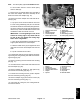
15. Use allen wrench to remove flat head socket screws
from the adapter (Fig. 25).
16. Remove adapter (6), bearing (7), both spacers (5)
from the belt drive housing (46) (Fig. 17).
17. Pull belt drive housing with the groomer adjuster
from the reel bearing housing (Fig. 25).
18. Remove adapter ring (9) and both slot covers (54)
from the reel bearing housing (Fig. 17).
19. If removing the cutting reel, see Cutting Reel Re-
moval in this section.
1. Flat head socket screw
2. Adapter
3. Belt drive housing
4. Groomer adjuster
5. Bedbar adjuster frame
6. Adapter ring
7. Reel bearing housing
8. Spacer
9. Reel bearing lock nut
10. Driven pulley (removed)
Figure 25
7
8
2
6
1
10
2
1
9
4
3
5
1. Bearing
2. Adapter ring
3. Reel bearing housing
4. Flat head socket screws
5. Adapter
6. Spacers
7. Belt drive housing
8. Slot cover
9. Lock nuts
10. Mounting block
11. Cap screw
12. Belleville washer
Figure 26
8
1
5
11
12
3
2
10
1
6
4
7
FRAME ASSEMBLY (LH)
9
Grooming Reel
Kit