
Service Manual


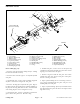


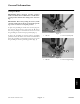

Table Of Contents
- Preface
- Table Of Contents
- 1 - Safety
- 2 - Product Records and Maintenance
- 3 - Engine
- Kawasaki FE120 Engine Service Manual
- 4 - Traction and Reel Drive System
- 5 - Electrical System
- 6 - Chassis and Controls
- 7 - Cutting Unit
- 8 - Groomer

Greensmaster Flex 18/21Page 7 – 24Cutting Unit
Side Plate Service
1. Crossmember
2. Adjuster shaft (2 used)
3. Thrust washer
4. Flange bushing (4 used)
5. Cap screw (2 used)
6. Lock washer (2 used)
7. Detent (2 used)
8. Wave washer (2 used)
9. Retaining ring (2 used)
10. Adjuster screw (2 used)
11. Washer (2 used)
12. Compression spring (2 used)
13. Lock nut (2 used)
14. LH side plate
15. Shoulder bolt (4 used)
16. Oil seal (4 used)
17. O–ring
18. Ball bearing (2 used)
19. RH side plate
20. Wave washer
21. Nylon bushing (2 used)
22. Rubber bushing (2 used)
23. Pitch bushing (2 used)
24. Retaining ring (2 used)
25. Square nut (4 used)
Figure 34
FRONT
RIGHT
1
13
12
11
10
9
8
4
21
22
5
7
16
17
18
16
23
4
2
23
16
25
14
19
16
24
18
20
3
24
15
6
210 to 240 in–lb
(23.7 to 27.1 N–m)
Disassembly (Fig. 34)
1. Remove side plate(s) from cutting unit (see Cutting
Reel Removal in this section).
2. Remove inner and outer grease seals (item 16) from
side plate.
3. On RH side plate, remove outer retaining ring (item
24) that secures the bearing in the side plate.
4. Remove bearing (item 18) from side plate. Inspect
bearing to insure that it spins freely and has minimal ax-
ial play. The bearing balls must be free of deformation
and scoring. Replace the bearing if necessary.
5. On LH side plate, remove o–ring (item 17) from the
groove in the side plate bore. Discard o–ring.
6. On RH side plate, remove wave washer (item 20)
and thrust washer (item 3) from side plate. Inner retain-
ing ring can remain in the side plate.
7. Remove all grease from the side plate bore. Thor-
oughly clean side plate. Inspect side plate and replace
if wear or damage is found.
8. Inspect pitch bushing for wear or damage. If neces-
sary, remove bushing from side plate and press new
bushing fully onto side plate.
9. Inspect nylon bushings (item 21) and rubber bush-
ings (item 22) in side plates. Remove and replace bush-
ings if necessary.