
Operator's Manual


1
InstallingtheCuttingUnits
Partsneededforthisprocedure:
1Righthoseguide
1
Lefthoseguide
Procedure
1.Parkthemachineonalevelsurface,engagethe
parkingbrake,shutofftheengine,andremove
thekeyfromtheignitionswitch.
2.Removethereelmotorsfromtheshipping
brackets.
3.Removeanddiscardtheshippingbrackets.
4.Removethecuttingunitsfromthecartons.
Assembleandadjustthemasdescribedinthe
cuttingunitOperator'sManual.
5.Makesurethatthecounterweight(Figure3)is
installedtotheproperendofthecuttingunitas
describedinthecuttingunitOperator'sManual.
g019938
Figure3
1.Counterweight
6.Allthecuttingunitsareshippedwiththeturf
compensationspringmountedtotheright
sideofthecuttingunit.Ensurethattheturf
compensationspringismountedtothesame
sideofthecuttingunitasthereeldrivemotor.
Positiontheturfcompensationasfollows:
A.Removethe2carriageboltsandnuts
securingtherodbrackettothecuttingunit
tabs(Figure4).
g003949
Figure4
1.Turfcompensationspring3.Springtube
2.Rodbracket
B.Removetheangenutsecuringthespring
tubebolttothecarrierframetab(Figure4),
andremovetheassembly.
C.Mountthespringtubebolttotheopposite
tabonthecarrierframeandsecureitwith
theangenut.
Note:Positiontheboltheadtotheouter
sideofthetabasshowninFigure4.
g003967
Figure5
1.Oppositecarrierframetab
2.Rodbracket
D.Mounttherodbrackettothecuttingunit
tabswiththecarriageboltsandnuts(Figure
5).
Note:Wheninstallingorremovingthecutting
units,makesurethatthehairpincotteris
installedinthespringrodholenexttotherod
bracket.Otherwise,installthehairpincotterin
theholeintheendoftherod.
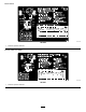
7.Oncuttingunit4(leftfront)andcuttingunit5
(rightfront),usetherod-bracketmountingnuts
toinstallthehoseguidestothefrontofthe
cutting-unittabs.Thehoseguidesshouldlean
towardthecentercuttingunit(Figure6,Figure
7,Figure8).
14