
Service Manual


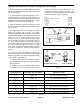


Table Of Contents
- Title Page
- Revision History
- Reader Comments
- Preface
- Table Of Contents
- 1 - Safety
- 2 - Product Records and Maintenance
- 3 - Kubota Diesel Engine
- 4 - Hydraulic System
- Specifications
- General Information
- Special Tools
- Hydraulic Schematics
- Hydraulic Flow Diagrams
- Troubleshooting
- Testing
- Traction Circuit Testing - Charge Pressure Test
- Traction Unit Testing - Wheel Motor Efficiency Tests
- Traction Circuit Testing - Piston Pump/Hydrostat Flow and Relief Pressure Test
- Cutting Unit Circuit Testing - Pressure Test
- Cutting Unit Circuit Testing - Reel Motor Efficiency/Case Drain Test
- Cutting Unit Circuit Testing - Reel Motor Cross-Over Relief Pressure Test (Reelmaster 3575-D)
- Cutting Unit Circuit Testing - Proportional Relief Valve (PRV) Pressure Test
- Cutting Unit Circuit Testing - Mow Control Manifold Relief Valve (RV) Pressure Test
- Cutting Unit Circuit Testing - Gear Pump (P1) Flow Test
- Steering/Lift Circuit Testing - Gear Pump (P2) Flow Test
- Steering/Lift Circuit Testing - Lift Relief Valve (RV1) Pressure Test (Reelmaster 3555-D and 3575-D)
- Steering/Lift Circuit Testing - Steering Relief Valve Pressure Test
- Steering/Lift Circuit Testing - Steering Control Valve and Steering Cylinder Test
- Adjustments
- Service and Repairs
- General Precautions for Removing and Installing Hydraulic System Components
- Check Hydraulic Lines and Hoses
- Priming Hydraulic Pumps
- Flush Hydraulic System
- Filtering Closed-Loop Traction Circuit
- Charge Hydraulic System
- Hydraulic Tank
- Radiator and Oil Cooler Assembly
- Hydraulic Pump Assembly
- Neutral Arm Assembly
- Piston Pump/Hydrostat
- Piston Pump/Hydrostat Service
- Gear Pump
- Gear Pump Service
- Front Wheel Motors
- Rear Wheel Motor
- Wheel Motor Service
- Cutting Unit Reel Motor
- Cutting Unit Reel Motor Service (Reelmaster 3550-D and 3555-D)
- Cutting Unit Reel Motor Service (Reelmaster 3575-D)
- Mow Control Manifold
- Mow Control Manifold Service
- Lift Control Manifold
- Lift Control Manifold Service (Reelmaster 3550-D)
- Lift Control Manifold Service (Reelmaster 3555-D and 3575-D)
- Control Manifold Cartridge Valve Service
- Steering Control Valve
- Steering Control Valve Service
- Steering Cylinder
- Steering Cylinder Service
- Front Lift Cylinders
- Rear Lift Cylinders
- Lift Cylinder Service
- 5 - Electrical System
- General Information
- Electrical Schematic
- Special Tools
- Troubleshooting
- Electrical System Quick Checks
- Adjustments
- Component Testing
- Ignition Switch
- Main Power Relay
- Fuses
- Fusible Links
- Toro Electronic Controller (TEC)
- Parking Brake Switch
- Neutral Switch
- Lower/Raise Joystick Switches
- Reel Enable/Disable Switch
- Mow/Transport Switch
- Seat Switch
- Backlap Switch
- Turn Around Switch (Reelmaster 3555-D and 3575-D)
- Engine Temperature Sender
- Start Relay
- Fuel Stop Solenoid
- Fuel Pump
- Glow Relay
- Hydraulic Solenoid Valve Coils
- Indicator Lights
- CAN-bus Termination Resistors
- Hour Meter
- Oil Pressure Switch
- Worklight Switch
- Service and Repairs
- 6 - Chassis
- 7 - DPA Cutting Units
- 8 - Belt Driven Groomer (Optional)
- 9 - Universal Groomer (Optional)
- 10 - Foldout Drawings
- Electrical Drawing Designations
- Reelmaster 3550-D Hydraulic Schematic
- Reelmaster 3555-D/3575-D Hydraulic Schematic
- Reelmaster 3550-D Electrical Schematic (machine serial numbers below 316000300)
- Reelmaster 3550-D (machine serial numbers above 316000300) Electrical Schematic
- Reelmaster 3555-D/3575-D Electrical Schematic
- Reelmaster 3550--D/3555--D/3575--D Electrical Schematic (Serial Numbers Above 403446001)
- Reelmaster 3550-D (machine serial numbers below 316000300) Wire Harness Drawing
- Reelmaster 3550-D (machine serial numbers below 316000300) Wire Harness Diagram
- Reelmaster 3550--D/3555--D/3575--D (Machine serial number 316000301 to 403446000) Wire Harness Drawing
- Reelmaster 3550-D (machine serial numbers above 316000300) Wire Harness Diagram
- Reelmaster 3550--D/3555--D/3575--D Wire Harness Drawing(Machine serial number 316000301 to 403446000)
- Reelmaster 3550--D/3555--D/3575--D Wire Harness Drawing Serial Numbers 403446001 to 405999999)
- Reelmaster 3550--D/3555--D/3575--D Wire Harness Drawing (Serial Numbers Above 406000000)

Reelmaster 3550−D/3555−D/3575−DHydraulic System Page 4 − 6
Hydraulic Fitting Installation (SAE Straight Thread O−Ring Fitting into Component Port)
Non−Adjustable Fitting (Fig. 4)
1. Make sure all threads and sealing surfaces of fitting
and component port are free of burrs, nicks, scratches
or any foreign material.
2. As a preventative measure against leakage, it is rec-
ommended that the O−ring be replaced any time the
connection is opened.
3. Lightly lubricate the O−ring with clean hydraulic oil.
Fitting threads should be clean with no lubricant applied.
IMPORTANT: Before installing fitting into port, de-
termine port material. If fitting is to be installed into
an aluminum port, installation torque is reduced.
4. Install the fitting into the port. Then, use a torque
wrench and socket to tighten the fitting to the recom-
mended installation torque (Fig. 5).
NOTE: Use of an offset wrench (e.g. crowfoot wrench)
will affect torque wrench calibration due to the effective
length change of the torque wrench. Tightening torque
when using a torque wrench with an offset wrench will
be less than the recommended installation torque. See
Using a Torque Wrench with an Offset Wrench in the
Torque Specifications section of Chapter 2 − Product
Records and Maintenance to determine necessary con-
version information.
5. If a torque wrench is not available, or if space at the
port prevents use of a torque wrench, an alternate meth-
od of assembly is the Flats From Finger Tight (F.F.F.T.)
method.
A. Install the fitting into the port and tighten it down
full length until finger tight.
B. If port material is steel, tighten the fitting to the
listed F.F.F.T. If port material is aluminum, tighten fit-
ting to 60% of listed F.F.F.T.
Size F.F.F.T.
4 (1/4 in. nominal hose or tubing) 1.00 +
0.25
6 (3/8 in.) 1.50 +
0.25
8 (1/2 in.) 1.50 +
0.25
10 (5/8 in.) 1.50 +
0.25
12 (3/4 in.) 1.50 +
0.25
16 (1 in.) 1.50 +
0.25
Figure 4
O−ring
Fitting
Fitting
Dash Size
Fitting Port Side
Thread Size
Installation Torque Into
Steel Port
Installation Torque Into
Aluminum Port
4 7/16 − 20 15 to 19 ft−lb (21 to 25 N−m) 9 to 11 ft−lb (13 to 15 N−m)
5 1/2 − 20 18 to 22 ft−lb (25 to 29 N−m) 11 to 15 ft−lb (15 to 20 N−m)
6 9/16 − 18 34 to 42 ft−lb (47 to 56 N−m) 20 to 26 ft−lb (28 to 35 N−m)
8 3/4 − 16 58 to 72 ft−lb (79 to 97 N−m) 35 to 43 ft−lb (48 to 58 N−m)
10 7/8 − 14 99 to 121 ft−lb (135 to 164 N−m) 60 to 74 ft−lb (82 to 100 N−m)
12 1 1/16 − 12 134 to 164 ft−lb (182 to 222 N−m) 81 to 99 ft−lb (110 to 134 N−m)
14 1 3/16 − 12 160 to 196 ft−lb (217 to 265 N−m) 96 to 118 ft−lb (131 to 160 N−m)
16 1 5/16 − 12 202 to 248 ft−lb (274 to 336 N−m) 121 to 149 ft−lb (165 to 202 N−m)
20 1 5/8 − 12 247 to 303 ft−lb (335 to 410 N−m) 149 to 183 ft−lb (202 to 248 N−m)
Figure 5