
Service Manual


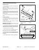
Table Of Contents
- Title Page
- Revision History
- Reader Comments
- Preface
- Table Of Contents
- 1 - Safety
- 2 - Product Records and Maintenance
- 3 - Kubota Diesel Engine
- 4 - Hydraulic System
- Specifications
- General Information
- Special Tools
- Hydraulic Schematics
- Hydraulic Flow Diagrams
- Troubleshooting
- Testing
- Traction Circuit Testing - Charge Pressure Test
- Traction Unit Testing - Wheel Motor Efficiency Tests
- Traction Circuit Testing - Piston Pump/Hydrostat Flow and Relief Pressure Test
- Cutting Unit Circuit Testing - Pressure Test
- Cutting Unit Circuit Testing - Reel Motor Efficiency/Case Drain Test
- Cutting Unit Circuit Testing - Reel Motor Cross-Over Relief Pressure Test (Reelmaster 3575-D)
- Cutting Unit Circuit Testing - Proportional Relief Valve (PRV) Pressure Test
- Cutting Unit Circuit Testing - Mow Control Manifold Relief Valve (RV) Pressure Test
- Cutting Unit Circuit Testing - Gear Pump (P1) Flow Test
- Steering/Lift Circuit Testing - Gear Pump (P2) Flow Test
- Steering/Lift Circuit Testing - Lift Relief Valve (RV1) Pressure Test (Reelmaster 3555-D and 3575-D)
- Steering/Lift Circuit Testing - Steering Relief Valve Pressure Test
- Steering/Lift Circuit Testing - Steering Control Valve and Steering Cylinder Test
- Adjustments
- Service and Repairs
- General Precautions for Removing and Installing Hydraulic System Components
- Check Hydraulic Lines and Hoses
- Priming Hydraulic Pumps
- Flush Hydraulic System
- Filtering Closed-Loop Traction Circuit
- Charge Hydraulic System
- Hydraulic Tank
- Radiator and Oil Cooler Assembly
- Hydraulic Pump Assembly
- Neutral Arm Assembly
- Piston Pump/Hydrostat
- Piston Pump/Hydrostat Service
- Gear Pump
- Gear Pump Service
- Front Wheel Motors
- Rear Wheel Motor
- Wheel Motor Service
- Cutting Unit Reel Motor
- Cutting Unit Reel Motor Service (Reelmaster 3550-D and 3555-D)
- Cutting Unit Reel Motor Service (Reelmaster 3575-D)
- Mow Control Manifold
- Mow Control Manifold Service
- Lift Control Manifold
- Lift Control Manifold Service (Reelmaster 3550-D)
- Lift Control Manifold Service (Reelmaster 3555-D and 3575-D)
- Control Manifold Cartridge Valve Service
- Steering Control Valve
- Steering Control Valve Service
- Steering Cylinder
- Steering Cylinder Service
- Front Lift Cylinders
- Rear Lift Cylinders
- Lift Cylinder Service
- 5 - Electrical System
- General Information
- Electrical Schematic
- Special Tools
- Troubleshooting
- Electrical System Quick Checks
- Adjustments
- Component Testing
- Ignition Switch
- Main Power Relay
- Fuses
- Fusible Links
- Toro Electronic Controller (TEC)
- Parking Brake Switch
- Neutral Switch
- Lower/Raise Joystick Switches
- Reel Enable/Disable Switch
- Mow/Transport Switch
- Seat Switch
- Backlap Switch
- Turn Around Switch (Reelmaster 3555-D and 3575-D)
- Engine Temperature Sender
- Start Relay
- Fuel Stop Solenoid
- Fuel Pump
- Glow Relay
- Hydraulic Solenoid Valve Coils
- Indicator Lights
- CAN-bus Termination Resistors
- Hour Meter
- Oil Pressure Switch
- Worklight Switch
- Service and Repairs
- 6 - Chassis
- 7 - DPA Cutting Units
- 8 - Belt Driven Groomer (Optional)
- 9 - Universal Groomer (Optional)
- 10 - Foldout Drawings
- Electrical Drawing Designations
- Reelmaster 3550-D Hydraulic Schematic
- Reelmaster 3555-D/3575-D Hydraulic Schematic
- Reelmaster 3550-D Electrical Schematic (machine serial numbers below 316000300)
- Reelmaster 3550-D (machine serial numbers above 316000300) Electrical Schematic
- Reelmaster 3555-D/3575-D Electrical Schematic
- Reelmaster 3550--D/3555--D/3575--D Electrical Schematic (Serial Numbers Above 403446001)
- Reelmaster 3550-D (machine serial numbers below 316000300) Wire Harness Drawing
- Reelmaster 3550-D (machine serial numbers below 316000300) Wire Harness Diagram
- Reelmaster 3550--D/3555--D/3575--D (Machine serial number 316000301 to 403446000) Wire Harness Drawing
- Reelmaster 3550-D (machine serial numbers above 316000300) Wire Harness Diagram
- Reelmaster 3550--D/3555--D/3575--D Wire Harness Drawing(Machine serial number 316000301 to 403446000)
- Reelmaster 3550--D/3555--D/3575--D Wire Harness Drawing Serial Numbers 403446001 to 405999999)
- Reelmaster 3550--D/3555--D/3575--D Wire Harness Drawing (Serial Numbers Above 406000000)

Reelmaster 3550--D/3555--D/3575--D
DPA Cutting Units
Page 7 -- 14
Leveling Rear Roller
The precision machined components of the cutting unit
frame keep the rear roller and cutting reel in alignment
(parallel). If the side plates are disassembled or as the
cutting reel wears, a limited amount of side plate adjust-
ment is possible to m ake sure that the cutting unit is
properly aligned.
1. Place the assembled cutting unit on a surface plate.
2. Make sure that bedknife is properly adjusted to cut-
ting reel.
3. Check if the rear roller is level to the cutting reel by
using a 0.005” (0.13 mm) feeler gauge to determine the
clearance between the surface plate and the rear roller
at each end of the roller. As the rear roller is rotated one
full turn, check if the feeler gauge will consistently pass
under the roller at one end but will not pass under the op-
posite end. Check rear roller with the feeler gauge just
inside the machined ends of the roller. A frame adjust-
ment should be made if there is consistently more than
0.005” (0.13 mm) clearance under the roller on one end
but not on the other.
NOTE: Cutting units with 5” diameter reel use two (2)
shoulder bolts to secure side plates to frame. Cutting
units with 7” diameter reel use three (3) shoulder bolts
to secure side plates to frame.
4. Loosen, but do not remove, shoulder bolts that se-
cure the side plate to the frame opposite the side that is
not level (Fig. 21).
5. Adjust the position of the side plate to parallel the
rear roller and cutting reel. Then, tighten the shoulder
bolts to a torque from 27 to 33 ft--lb (37 to 44 N--m).
6. After tightening the side plate, recheck the rear roller.
If necessary, loosen and adjust second side plate.
7. If rear roller is still not level after adjusting both side
plates, check to see if cutting reel is tapered (see Pre-
paring Reel for Grinding in this chapter). If cutting reel is
not tapered and rear roller is not level, a 0.010” shim
(part number 107-- 4001) is available to allow additional
rear roller adjustment. The shim would be used on one
side of the rear roller and should be installed between
the rear roller bracket and roller shim (Fig. 22). Tighten
the flange nuts to a torque from 15 to 19 ft--lb (20 to 26
N--m)
8. After leveling rear roller, complete cutting unit set--up
and adjustment sequence.
1. Shoulder bolt
2. Side plate
3. Rear roller
Figure 21
11
3
2
1
2
3
4
7
8
6
5
1. Rear roller assembly
2. Rear roller bracket
3. Carriage screw (4)
4. Flange nut (4)
5. Flat washer (4)
6. Roller shims (in storage
above side plate)
7. Roller shims (in use
below side plate)
8. 0.010” shim (if needed)
Figure 22
15 to 19 ft--lb
(20 to 26 N --m)