
Service Manual


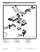


Table Of Contents
- Title Page
- Revision History
- Reader Comments
- Preface
- Table Of Contents
- 1 - Safety
- 2 - Product Records and Maintenance
- 3 - Kubota Diesel Engine
- 4 - Hydraulic System
- Specifications
- General Information
- Special Tools
- Hydraulic Schematics
- Hydraulic Flow Diagrams
- Troubleshooting
- Testing
- Traction Circuit Testing - Charge Pressure Test
- Traction Unit Testing - Wheel Motor Efficiency Tests
- Traction Circuit Testing - Piston Pump/Hydrostat Flow and Relief Pressure Test
- Cutting Unit Circuit Testing - Pressure Test
- Cutting Unit Circuit Testing - Reel Motor Efficiency/Case Drain Test
- Cutting Unit Circuit Testing - Reel Motor Cross-Over Relief Pressure Test (Reelmaster 3575-D)
- Cutting Unit Circuit Testing - Proportional Relief Valve (PRV) Pressure Test
- Cutting Unit Circuit Testing - Mow Control Manifold Relief Valve (RV) Pressure Test
- Cutting Unit Circuit Testing - Gear Pump (P1) Flow Test
- Steering/Lift Circuit Testing - Gear Pump (P2) Flow Test
- Steering/Lift Circuit Testing - Lift Relief Valve (RV1) Pressure Test (Reelmaster 3555-D and 3575-D)
- Steering/Lift Circuit Testing - Steering Relief Valve Pressure Test
- Steering/Lift Circuit Testing - Steering Control Valve and Steering Cylinder Test
- Adjustments
- Service and Repairs
- General Precautions for Removing and Installing Hydraulic System Components
- Check Hydraulic Lines and Hoses
- Priming Hydraulic Pumps
- Flush Hydraulic System
- Filtering Closed-Loop Traction Circuit
- Charge Hydraulic System
- Hydraulic Tank
- Radiator and Oil Cooler Assembly
- Hydraulic Pump Assembly
- Neutral Arm Assembly
- Piston Pump/Hydrostat
- Piston Pump/Hydrostat Service
- Gear Pump
- Gear Pump Service
- Front Wheel Motors
- Rear Wheel Motor
- Wheel Motor Service
- Cutting Unit Reel Motor
- Cutting Unit Reel Motor Service (Reelmaster 3550-D and 3555-D)
- Cutting Unit Reel Motor Service (Reelmaster 3575-D)
- Mow Control Manifold
- Mow Control Manifold Service
- Lift Control Manifold
- Lift Control Manifold Service (Reelmaster 3550-D)
- Lift Control Manifold Service (Reelmaster 3555-D and 3575-D)
- Control Manifold Cartridge Valve Service
- Steering Control Valve
- Steering Control Valve Service
- Steering Cylinder
- Steering Cylinder Service
- Front Lift Cylinders
- Rear Lift Cylinders
- Lift Cylinder Service
- 5 - Electrical System
- General Information
- Electrical Schematic
- Special Tools
- Troubleshooting
- Electrical System Quick Checks
- Adjustments
- Component Testing
- Ignition Switch
- Main Power Relay
- Fuses
- Fusible Links
- Toro Electronic Controller (TEC)
- Parking Brake Switch
- Neutral Switch
- Lower/Raise Joystick Switches
- Reel Enable/Disable Switch
- Mow/Transport Switch
- Seat Switch
- Backlap Switch
- Turn Around Switch (Reelmaster 3555-D and 3575-D)
- Engine Temperature Sender
- Start Relay
- Fuel Stop Solenoid
- Fuel Pump
- Glow Relay
- Hydraulic Solenoid Valve Coils
- Indicator Lights
- CAN-bus Termination Resistors
- Hour Meter
- Oil Pressure Switch
- Worklight Switch
- Service and Repairs
- 6 - Chassis
- 7 - DPA Cutting Units
- 8 - Belt Driven Groomer (Optional)
- 9 - Universal Groomer (Optional)
- 10 - Foldout Drawings
- Electrical Drawing Designations
- Reelmaster 3550-D Hydraulic Schematic
- Reelmaster 3555-D/3575-D Hydraulic Schematic
- Reelmaster 3550-D Electrical Schematic (machine serial numbers below 316000300)
- Reelmaster 3550-D (machine serial numbers above 316000300) Electrical Schematic
- Reelmaster 3555-D/3575-D Electrical Schematic
- Reelmaster 3550--D/3555--D/3575--D Electrical Schematic (Serial Numbers Above 403446001)
- Reelmaster 3550-D (machine serial numbers below 316000300) Wire Harness Drawing
- Reelmaster 3550-D (machine serial numbers below 316000300) Wire Harness Diagram
- Reelmaster 3550--D/3555--D/3575--D (Machine serial number 316000301 to 403446000) Wire Harness Drawing
- Reelmaster 3550-D (machine serial numbers above 316000300) Wire Harness Diagram
- Reelmaster 3550--D/3555--D/3575--D Wire Harness Drawing(Machine serial number 316000301 to 403446000)
- Reelmaster 3550--D/3555--D/3575--D Wire Harness Drawing Serial Numbers 403446001 to 405999999)
- Reelmaster 3550--D/3555--D/3575--D Wire Harness Drawing (Serial Numbers Above 406000000)

Reelmaster 3550−D/3555−D/3575−D Hydraulic SystemPage 4 − 133
Removal (Fig. 85)
1. Park machine on a level surface. Lower cutting units,
stop engine and engage parking brake. Remove key
from the ignition switch.
2. Read the General Precautions for Removing and
Installing Hydraulic System Components in this chapter.
3. To prevent contamination of hydraulic system during
lift cylinder removal, thoroughly clean exterior of cylin-
der and fittings.
WARNING
Make sure that the cutting units are fully lowered
before loosening hydraulic lines from lift cylin-
ders. If cutting units are not fully lowered as hy-
draulic lines are loosened, cutting units may
drop unexpectedly.
NOTE: To ease installation, label the hydraulic hoses to
show their correct position on the lift cylinder.
4. Disconnect hydraulic hoses from lift cylinder that is
to be removed.
5. Detach rod end of lift cylinder from lift arm. Remove
retaining ring and flat washer from one end of the cylin-
der pin and slide pin from lift arm and cylinder rod end.
6. Remove washer head screw that secures the pivot
pin to the frame and slide pivot pin from frame and cylin-
der.
7. Remove lift cylinder from machine.
8. If necessary, remove hydraulic fittings from lift cylin-
der and discard O−rings.
Installation (Fig. 85)
1. If fittings were removed from lift cylinder, lubricate
and place new O−rings onto fittings. Install fittings into
cylinder port openings using marks made during the re-
moval process to properly orientate fittings. Tighten fit-
tings (see Hydraulic Fitting Installation in this chapter).
2. Secure barrel end of cylinder to frame and slide pivot
pin into frame and cylinder. Secure pivot pin to frame
with washer head screw.
3. Make sure that flat washer and retaining ring are in-
stalled on one end of the cylinder pin.
4. Position cylinder rod end to lift arm and insert pin
through lift arm and cylinder rod end. Secure pin to lift
arm with second flat washer and retaining ring.
5. Attach hydraulic hoses to lift cylinder (see Hydraulic
Hose and Tube Installation in this chapter).
6. Fill reservoir with hydraulic fluid as required.
7. After installation is completed, operate lift cylinder to
verify cylinder, hydraulic hose and fitting clearance.
Hydraulic
System